Overshoot Goal
Purpose
Limit overshoot in the step response from specified inputs to specified outputs, when using Control System Tuner.
Description
Overshoot Goal limits the overshoot in the step response between the specified signal locations. The constraint is satisfied when the overshoot in the tuned response is less than the target overshoot
The software maps the maximum overshoot to a peak gain constraint, assuming second-order system characteristics. Therefore, for tuning higher-order systems, the overshoot constraint is only approximate. In addition, the Overshoot Goal cannot reliably reduce the overshoot below 5%.
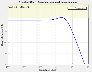
When you create a tuning goal in Control System Tuner, a tuning-goal plot is generated. The shaded area on the plot represents the region in the frequency domain where the tuning goal is not satisfied.
Creation
In the Tuning tab of Control System Tuner, select New Goal > Maximum overshoot to create an Overshoot Goal.
Command-Line Equivalent
When tuning control systems at the command line, use TuningGoal.Overshoot to specify a step response goal.
Response Selection
Use this section of the dialog box to specify input, output, and loop-opening locations for evaluating the tuning goal.
Specify step-response inputs
Select one or more signal locations in your model at which to apply the step input. To constrain a SISO response, select a single-valued input signal. For example, to constrain the step response from a location named
'u'to a location named'y', click Add signal to list and select
 'u'. To constrain a MIMO response, select multiple signals or a vector-valued signal.Specify step-response outputs
Select one or more signal locations in your model at which to measure the response to the step input. To constrain a SISO response, select a single-valued output signal. For example, to constrain the step response from a location named
'u'to a location named'y', click
Add signal to list and select 'y'. To constrain a MIMO response, select multiple signals or a vector-valued signal. For MIMO systems, the number of outputs must equal the number of inputs.Evaluate overshoot with the following loops open
Select one or more signal locations in your model at which to open a feedback loop for the purpose of evaluating this tuning goal. The tuning goal is evaluated against the open-loop configuration created by opening feedback loops at the locations you identify. For example, to evaluate the tuning goal with an opening at a location named
'x', click
Add signal to list and select 'x'.
Tip
To highlight any selected signal in the Simulink® model, click ![]() . To remove a signal from the input or output list, click
. To remove a signal from the input or output list, click ![]() . When you have selected multiple signals, you can reorder
them using
. When you have selected multiple signals, you can reorder
them using ![]() and
and ![]() . For more information on how to specify signal locations
for a tuning goal, see
Specify Goals for Interactive Tuning.
. For more information on how to specify signal locations
for a tuning goal, see
Specify Goals for Interactive Tuning.
Options
Use this section of the dialog box to specify additional characteristics of the overshoot goal.
Limit % overshoot to
Enter the maximum percent overshoot. Overshoot Goal cannot reliably reduce the overshoot below 5%
Adjust for step amplitude
For a MIMO tuning goal, when the choice of units results in a mix of small and large signals in different channels of the response, this option allows you to specify the relative amplitude of each entry in the vector-valued step input. This information is used to scale the off-diagonal terms in the transfer function from reference to tracking error. This scaling ensures that cross-couplings are measured relative to the amplitude of each reference signal.
For example, suppose that tuning goal is that outputs
'y1' and 'y2'track reference signals'r1'and 'r2'. Suppose further that you require the outputs to track the references with less than 10% cross-coupling. Ifr1andr2have comparable amplitudes, then it is sufficient to keep the gains fromr1toy2andr2andy1below 0.1. However, ifr1is 100 times larger thanr2, the gain fromr1toy2must be less than 0.001 to ensure thatr1changesy2by less than 10% of ther2target. To ensure this result, set Adjust for step amplitude toYes. Then, enter[100,1]in the Amplitudes of step commands text box. Doing so tells Control System Tuner to take into account that the first reference signal is 100 times greater than the second reference signal.The default value,
No, means no scaling is applied.Apply goal to
Use this option when tuning multiple models at once, such as an array of models obtained by linearizing a Simulink model at different operating points or block-parameter values. By default, active tuning goals are enforced for all models. To enforce a tuning requirement for a subset of models in an array, select Only Models. Then, enter the array indices of the models for which the goal is enforced. For example, suppose you want to apply the tuning goal to the second, third, and fourth models in a model array. To restrict enforcement of the requirement, enter
2:4in the Only Models text box.For more information about tuning for multiple models, see Robust Tuning Approaches (Robust Control Toolbox).
Algorithms
When you tune a control system, the software converts each tuning goal into a normalized scalar value f(x). Here, x is the vector of free (tunable) parameters in the control system. The software then adjusts the parameter values to minimize f(x) or to drive f(x) below 1 if the tuning goal is a hard constraint.
For Overshoot Goal, f(x) reflects the relative satisfaction or violation of the goal. The percent deviation from f(x) = 1 roughly corresponds to the percent deviation from the specified overshoot target. For example, f(x) = 1.2 means the actual overshoot exceeds the target by roughly 20%, and f(x) = 0.8 means the actual overshoot is about 20% less than the target.
Overshoot Goal uses as a proxy for the overshoot, based on second-order model characteristics. Here, T is the closed-loop transfer function that the requirement constrains. The overshoot is tuned in the range from 5% ( = 1) to 100% (). Overshoot Goal is ineffective at forcing the overshoot below 5%.
This tuning goal also imposes an implicit stability constraint on the closed-loop transfer function between the specified inputs to outputs, evaluated with loops opened at the specified loop-opening locations. The dynamics affected by this implicit constraint are the stabilized dynamics for this tuning goal. The Minimum decay rate and Maximum natural frequency tuning options control the lower and upper bounds on these implicitly constrained dynamics. If the optimization fails to meet the default bounds, or if the default bounds conflict with other requirements, on the Tuning tab, use Tuning Options to change the defaults.