Design Compensator for Systems Represented by Frequency Response Data
This example shows how to design a compensator for a plant model defined by frequency response data (FRD) using Control System Designer.
Acquire Frequency Response Data (FRD) Plant Model
Nonparametric representations of plant models, such as frequency response data, are often used for analysis and control design. These FRD models are typically obtained from:
1) Signal analyzer hardware that performs frequency domain measurements on systems.
2) Nonparametric estimation techniques using the systems time response data. You can use the following products to estimate FRD models.
Simulink® Control Design™:
Function:
frestimate(Simulink Control Design)Example: Frequency Response Estimation Using Simulation-Based Techniques (Simulink Control Design).
Signal Processing Toolbox™:
Function:
tfestimate(Signal Processing Toolbox).
System Identification Toolbox™:
FRD Model and Design Requirements
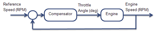
In this example, design an engine speed controller that actuates the engine throttle angle:
The frequency response of the engine is already estimated. Load and view the data.
load FRDPlantDemoData.mat
AnalyzerData
AnalyzerData = struct with fields:
Response: [594×1 double]
Frequency: [594×1 double]
FrequencyUnits: 'rad/s'
Create an FRD model object:
FRDPlant = frd(AnalyzerData.Response,AnalyzerData.Frequency,...
    'Unit',AnalyzerData.FrequencyUnits);
The design requirements are:
Zero steady-state error for step reference speed changes
Phase margin greater than 60 degrees
Gain margin greater than 20 dB.
Design Compensator
Open Control System Designer.
controlSystemDesigner({'bode','nichols'},FRDPlant)
The app opens with both Bode and Nichols open-loop editors.
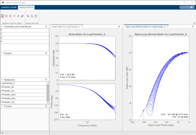
You can design the compensator by shaping the open-loop frequency response in either the Bode editor or Nichols editor. In these editors, interactively modify the gain, poles, and zeros of the compensator.
To satisfy the tracking requirement of zero steady-state error, add an integrator to the compensator. Right-click the Bode editor plot area, and select Add Pole/Zero > Integrator.
To meet the gain and phase margin requirements, add a zero to the compensator. Right-click the Bode editor plot area, and select Add Pole/Zero > Real Zero. Modify the location of the zero and the gain of the compensator until you satisfy the margin requirements.
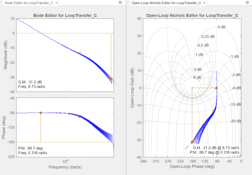
One possible design that satisfies the design requirements is:
This compensator design, which is a PI controller, achieves a 20.7 dB gain margin and a 70.8 degree phase margin.
Export the designed compensator to the workspace. Click Export.
Validate the Design
Validate the controller performance by simulating the engine response using a nonlinear model in Simulink. For this example, the validation simulation results are in EngineStepResponse.
Plot the response of the engine to a reference speed change from 2000 to 2500 RPM:
plot(EngineStepResponse.Time,EngineStepResponse.Speed)
title('Engine Step Response')
xlabel('Time (s)')
ylabel('Engine Speed (RPM)')
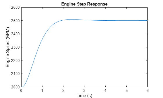
The response shows zero steady-state error and well-behaved transients with the following metrics.
stepinfo(EngineStepResponse.Speed,EngineStepResponse.Time)
ans = struct with fields:
         RiseTime: 0.7136
    TransientTime: 1.7194
     SettlingTime: 1.3738
      SettlingMin: 2.2505e+03
      SettlingMax: 2.5078e+03
        Overshoot: 0.3127
       Undershoot: 0
             Peak: 2.5078e+03
         PeakTime: 2.3853