Trimming and Linearization of the HL-20 Airframe
This is Part 1 of a five-part example series on design and tuning of the flight control system for the HL-20 vehicle. This part deals with trimming and linearization of the airframe.
HL-20 Model
The HL-20 model is adapted from the model described in NASA HL-20 Lifting Body Airframe (Aerospace Blockset). This is a 6-DOF model of the vehicle during the final descent and landing phase of the flight. No thrust is used during this phase and the airframe is gliding to the landing strip.
open_system('csthl20_trim')
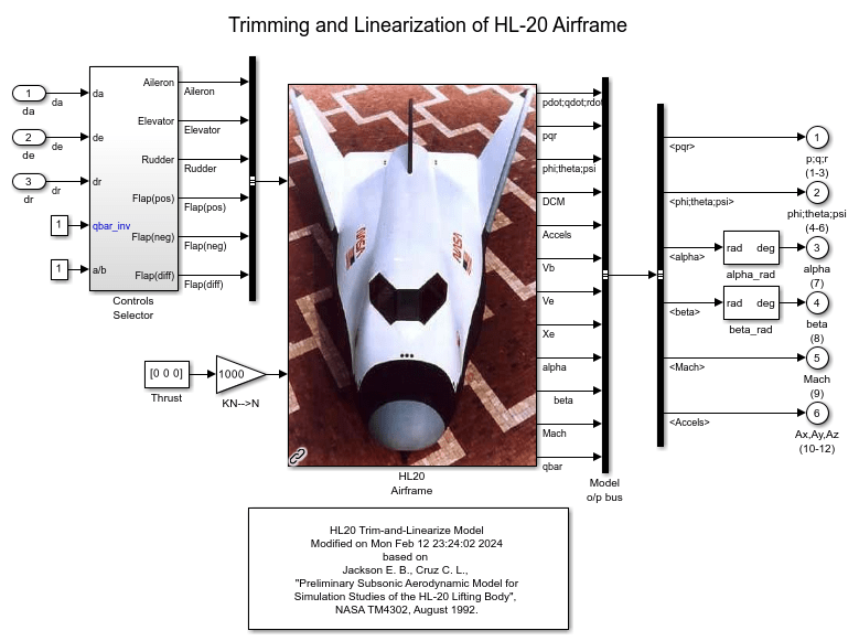
This version of the model includes the equations of motion (EOM), the force and moment calculation from the aerodynamic tables, the environment model, and the "Controls Selector" block which maps aileron, elevator, and rudder demands to deflections of the six control surfaces.
Batch Trimming
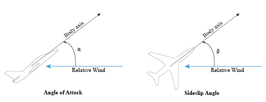
Trimming consists of calculating aileron, elevator, and rudder deflections that zero out the forces and moments on the airframe, or equivalently, keep the body velocities ub,vb,wb and angular rates p,q,r steady. Because thrust is not used during descent, one degree-of-freedom is lost and the trim condition must be relaxed to let ub to vary. The trim values of the deflections da,de,dr depend on the airframe orientation relative to the wind. This orientation is characterized by the angle-of-attack (AoA) alpha and the sideslip angle (AoS) beta.
With the operspec and findop functions, you can efficiently compute the trim deflections over a grid of (alpha,beta) values covering the operating range of the vehicle. Here we trim the model for 8 values of alpha ranging from -10 to 25 degrees, and 5 values of beta ranging from -10 to +10 degrees. The nominal altitude and speed are set to 10,000 feet and Mach 0.6.
d2r = pi/180;            % degrees to radians
m2ft = 3.28084;          % meter to feet
Altitude = 10000/m2ft;   % Nominal altitude
Mach = 0.6;              % Nominal Mach
alpha_vec = -10:5:25;	 % Alpha Range
beta_vec = -10:5:10;     % Beta Range
[alpha,beta] = ndgrid(alpha_vec,beta_vec);   % (Alpha,Beta) grid
Use operspec to create an array of operating point specifications.
opspec = operspec('csthl20_trim',size(alpha));

opspec(1)
ans =


 Operating point specification for the Model csthl20_trim.
 (Time-Varying Components Evaluated at time t=0)

States:
----------
     x         Known    SteadyState     Min         Max        dxMin       dxMax
___________ ___________ ___________ ___________ ___________ ___________ ___________

(1.) csthl20_trim/HL20 Airframe/6DOF (Euler Angles)/Calculate DCM & Euler Angles/phi theta psi
     0         false       true        -Inf         Inf        -Inf         Inf
 -0.19945      false       true        -Inf         Inf        -Inf         Inf
     0         false       true        -Inf         Inf        -Inf         Inf
(2.) csthl20_trim/HL20 Airframe/6DOF (Euler Angles)/p,q,r
     0         false       true        -Inf         Inf        -Inf         Inf
     0         false       true        -Inf         Inf        -Inf         Inf
     0         false       true        -Inf         Inf        -Inf         Inf
(3.) csthl20_trim/HL20 Airframe/6DOF (Euler Angles)/ub,vb,wb
  202.67       false       true        -Inf         Inf        -Inf         Inf
     0         false       true        -Inf         Inf        -Inf         Inf
  23.257       false       true        -Inf         Inf        -Inf         Inf
(4.) csthl20_trim/HL20 Airframe/6DOF (Euler Angles)/xe,ye,ze
-12071.9115    false       true        -Inf         Inf        -Inf         Inf
     0         false       true        -Inf         Inf        -Inf         Inf
-3047.9999     false       true        -Inf         Inf        -Inf         Inf

Inputs:
----------
  u   Known  Min   Max
_____ _____ _____ _____

(1.) csthl20_trim/da
  0   false -Inf   Inf
(2.) csthl20_trim/de
  0   false -Inf   Inf
(3.) csthl20_trim/dr
  0   false -Inf   Inf

Outputs:
----------
        y               Known              Min               Max             Period       PeriodicTolerance
_________________ _________________ _________________ _________________ _________________ _________________

(1.) csthl20_trim/p;q;r (1-3)
        0               false             -Inf               Inf               -1              0.0001
        0               false             -Inf               Inf               -1              0.0001
        0               false             -Inf               Inf               -1              0.0001
(2.) csthl20_trim/phi;theta;psi (4-6)
        0               false             -Inf               Inf               -1              0.0001
        0               false             -Inf               Inf               -1              0.0001
        0               false             -Inf               Inf               -1              0.0001
(3.) csthl20_trim/alpha (7)
        0               false             -Inf               Inf               -1              0.0001
(4.) csthl20_trim/beta (8)
        0               false             -Inf               Inf               -1              0.0001
(5.) csthl20_trim/Mach (9)
        0               false             -Inf               Inf               -1              0.0001
(6.) csthl20_trim/Ax,Ay,Az (10-12)
        0               false             -Inf               Inf               -1              0.0001
        0               false             -Inf               Inf               -1              0.0001
        0               false             -Inf               Inf               -1              0.0001
Specify the equilibrium conditions for each orientation of the airframe. To do this:
Specify the orientation by fixing the outputs alpha and beta to their desired values.
Specify the airframe speed by fixing the Mach output to 0.6.
Mark the angular rates p,q,r as steady.
Mark the velocities vb and wb as steady.
for ct=1:40
   % Specify alpha angle
   opspec(ct).Outputs(3).y = alpha(ct);
   opspec(ct).Outputs(3).Known = true;
   % Specify beta angle
   opspec(ct).Outputs(4).y = beta(ct);
   opspec(ct).Outputs(4).Known = true;
   % Specify Mach speed
   opspec(ct).Outputs(5).y = Mach;
   opspec(ct).Outputs(5).Known = true;
   % Mark p,q,r as steady
   opspec(ct).States(2).SteadyState = true(3,1);
   % Mark vb,wb as steady
   opspec(ct).States(3).SteadyState = [false;true;true];
   % (phi,theta,psi) and (Xe,Ye,Ze) are not steady
   opspec(ct).States(1).SteadyState = false(3,1);
   opspec(ct).States(4).SteadyState = false(3,1);
end
To fully characterize the trim condition, also
Set p=0 to prevent rolling.
Set the roll/pitch/yaw angles (phi,theta,psi) to (0,alpha,beta) to align the wind and earth frames.
Specify the airframe position (Xe,Ye,Ze) as (0,0,-Altitude).
for ct=1:40
   % Set (phi,theta,psi) to (0,alpha,beta)
   opspec(ct).States(1).x = [0 ; alpha(ct)*d2r ; beta(ct)*d2r];
   opspec(ct).States(1).Known = true(3,1);
   % Set p=0 (no rolling)
   opspec(ct).States(2).x(1) = 0;
   opspec(ct).States(2).Known(1) = true;
   % Set (Xe,Ye,Ze) to (0,0,-Altitude)
   opspec(ct).States(4).x = [0 ; 0 ; -Altitude];
   opspec(ct).States(4).Known = true(3,1);
end
Now use findop to compute the trim conditions for all 40 (alpha,beta) combinations in one go. This batch mode approach involves a single compilation of the model. FINDOP uses optimization to solve the nonlinear equations characterizing each equilibrium. Here we use the "SQP" algorithm for this task.
% Set options for FINDOP solver
TrimOptions = findopOptions;
TrimOptions.OptimizationOptions.Algorithm = 'sqp';
TrimOptions.DisplayReport = 'off';

% Trim model
[ops,rps] = findop('csthl20_trim',opspec,TrimOptions);
This returns 8-by-5 arrays OPS (operating conditions) and RPS (optimization reports). You can use RPS to verify that each trim condition was successfully calculated. Results for the first (alpha,beta) pair are shown below.
[alpha(1) beta(1)]
ans =

   -10   -10
ops(1)
ans =


 Operating point for the Model csthl20_trim.
 (Time-Varying Components Evaluated at time t=0)

States:
----------
    x
__________

(1.) csthl20_trim/HL20 Airframe/6DOF (Euler Angles)/Calculate DCM & Euler Angles/phi theta psi
    0
 -0.17453
 -0.17453
(2.) csthl20_trim/HL20 Airframe/6DOF (Euler Angles)/p,q,r
    0
 -0.15825
 0.008004
(3.) csthl20_trim/HL20 Airframe/6DOF (Euler Angles)/ub,vb,wb
 191.0911
 -34.2143
 -33.6945
(4.) csthl20_trim/HL20 Airframe/6DOF (Euler Angles)/xe,ye,ze
    0
    0
-3047.9999

Inputs:
----------
   u
________

(1.) csthl20_trim/da
-23.9841
(2.) csthl20_trim/de
-6.4896
(3.) csthl20_trim/dr
 4.0858
rps(1).TerminationString
ans =

    'Operating point search completed successfully using optimization.'
Batch Linearization
The gains of the flight control system are typically scheduled as a function of alpha and beta, see Part 2 (Angular Rate Control in the HL-20 Autopilot) for more details. To tune these gains, you need linearized models of the HL-20 airframe at the 40 trim conditions. Use linearize to compute these models from the trim operating conditions ops.
% Linearize airframe dynamics at each trim condition
G = linearize('csthl20_trim','csthl20_trim/HL20 Airframe',ops);

size(G)
8x5 array of state-space models.
Each model has 34 outputs, 9 inputs, and 12 states.
The linear equivalent of the "Controls Selector" block depends on the amount of elevator deflection and should be computed for qbar_inv=1 (nominal dynamic pressure at Mach=0.6). For convenience, also linearize this block at the 40 trim conditions.
CS = linearize('csthl20_trim','csthl20_trim/Controls Selector',ops);

% Zero out a/b and qbar_inv channels
CS = [CS(:,1:3) zeros(6,2)];
Linear Model Simplification
The linearized airframe models have 12 states:
xG = G.StateName
xG =

  12×1 cell array

    {'phi theta psi(1)'}
    {'phi theta psi(2)'}
    {'phi theta psi(3)'}
    {'p,q,r (1)'       }
    {'p,q,r (2)'       }
    {'p,q,r (3)'       }
    {'ub,vb,wb(1)'     }
    {'ub,vb,wb(2)'     }
    {'ub,vb,wb(3)'     }
    {'xe,ye,ze(1)'     }
    {'xe,ye,ze(2)'     }
    {'xe,ye,ze(3)'     }
Some states are not under the authority of the roll/pitch/yaw autopilot and other states contribute little to the design of this autopilot. For control purposes, the most important states are the roll angle phi, the body velocities ub,vb,wb, and the angular rates p,q,r. Accordingly, use xelim to obtain a 7th-order model that only retains these states.
G7 = G;
xKeep = {...
   'phi theta psi(1)'
   'ub,vb,wb(1)'
   'ub,vb,wb(2)'
   'ub,vb,wb(3)'
   'p,q,r (1)'
   'p,q,r (2)'
   'p,q,r (3)'};
[~,xElim] = setdiff(xG,xKeep);
for ct=1:40
   G7(:,:,ct) = xelim(G(:,:,ct),xElim,'Truncate');
end
With these linearized models in hand, you can move to the task of tuning and scheduling the flight control system gains. See Angular Rate Control in the HL-20 Autopilot for Part 2 of this example.