Packetized Modem with Data Link Layer
This example shows you how to implement a packetized modem with data link layer [ 1 ]. The modem features a packet-based physical layer and an ALOHA-based data link layer. You can either simulate the system or measure the system performance with software defined radio (SDR) hardware.
Required Hardware and Software
By default, this example will simulate the system performance. Optionally, you can measure system performance with one of the following SDR devices and the corresponding support package:
200-Series USRP Radio (B2xx or N2xx) and USRP Radio. For information on how to map an NI™ USRP device to an Ettus Research 200-series USRP device, see Supported Hardware and Required Software.
300-Series USRP Radio (X3xx) and Wireless Testbench. For information on how to map an NI USRP device to an Ettus Research 300-series USRP device, see Supported Radio Devices (Wireless Testbench).
To run the example using an SDR device, see Run Using Radios.
Introduction
Packetized wireless modems are communications systems that transmit information in bursts, known as packets, through a wireless channel. Each modem or node contains a physical layer where the modem modulates, transmits, and receives on a shared frequency band, and then demodulates the packets. Since all nodes use the same frequency band, a medium access control (MAC) algorithm is required to reduce the packet loss due to collisions (i.e. simultaneous transmissions). The data link layer includes a MAC sublayer and a logical link control sublayer that share the same channel and provide an error-free link between two nodes. The data link layer (layer 2) is between the network layer (layer 3) and the physical layer (layer 1).
Run Example
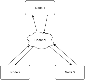
The example code creates three packetized modem node objects and connects them through a channel object. Each node sends packets to the other two nodes. ACKTimeout determines the timeout duration before a node decides the DATA packet transmission was not successful. ACKTimeout must be greater than the round trip duration for a DATA-ACK exchange, which is 0.21 seconds for this example. The simulation is time-based and simulates the full physical layer processing together with the data link layer.
Set Simulation Parameters
runDuration = 10;         % Seconds
numPayloadBits = 19530;   % Bits
packetArrivalRate = 0.2;  % Packets per second
ackTimeOut = 0.25;        % ACK time out in seconds
maxBackoffTime = 10;      % Maximum backoff time in ackTimeOut durations
mMaxDataRetries = 5;      % Maximum DATA retries
queueSize = 10;           % data link layer queue size in packets
samplesPerFrame = 2000;   % Number of samples processed every iteration
verbose = true;           % Print packet activity to command line
sampleRate = 200e3;
Fix random number generation seed for repeatable simulations.
rng(12345)
Create packetized modem nodes using the helperPacketizedModemNode object.
node1 = helperPacketizedModemNode('Address',1, ...
    'DestinationList',[2, 3],'NumPayloadBits',numPayloadBits, ...
    'PacketArrivalRate',packetArrivalRate,'ACKTimeOut',ackTimeOut, ...
    'MaxBackoffTime',maxBackoffTime,'MaxDataRetries',mMaxDataRetries, ...
    'QueueSize',queueSize,'CarrierDetectorThreshold',1e-5, ...
    'AGCMaxPowerGain',65,'SamplesPerFrame',samplesPerFrame, ...
    'Verbose',verbose,'SampleRate',sampleRate);
node2 = helperPacketizedModemNode('Address',2, ...
    'DestinationList',[1 3],'NumPayloadBits',numPayloadBits, ...
    'PacketArrivalRate',packetArrivalRate,'ACKTimeOut',ackTimeOut, ...
    'MaxBackoffTime',maxBackoffTime,'MaxDataRetries',mMaxDataRetries, ...
    'QueueSize',queueSize,'CarrierDetectorThreshold',1e-5, ...
    'AGCMaxPowerGain',65,'SamplesPerFrame',samplesPerFrame, ...
    'Verbose',verbose,'SampleRate',sampleRate);
node3 = helperPacketizedModemNode('Address',3, ...
    'DestinationList',[1 2],'NumPayloadBits',numPayloadBits, ...
    'PacketArrivalRate',packetArrivalRate,'ACKTimeOut',ackTimeOut, ...
    'MaxBackoffTime',maxBackoffTime,'MaxDataRetries',mMaxDataRetries, ...
    'QueueSize',queueSize,'CarrierDetectorThreshold',1e-5, ...
    'AGCMaxPowerGain',65,'SamplesPerFrame',samplesPerFrame, ...
    'Verbose',verbose,'SampleRate',sampleRate);
Configure the propagation channel using the helperMultiUserChannel object.
channel = helperMultiUserChannel( ...
    'NumNodes',3,'EnableTimingSkew',true,'DelayType','Triangle', ...
    'TimingError',20,'EnableFrequencyOffset',true, ...
    'PhaseOffset',47,'FrequencyOffset',2000,'EnableAWGN',true, ...
    'EbNo',25,'BitsPerSymbol',2,'SamplesPerSymbol',4, ...
    'EnableRicianMultipath', true, ...
    'PathDelays',[0 node1.SamplesPerSymbol/node1.SampleRate], ...
    'AveragePathGains',[15 0],'KFactor',15,'MaximumDopplerShift',10, ...
    'SampleRate',node1.SampleRate);
Main Simulation Loop
radioTime = 0;
nodeInfo = info(node1);
frameDuration = node1.SamplesPerFrame/node1.SampleRate;
[rcvd1,rcvd2,rcvd3] = deal(complex(zeros(node1.SamplesPerFrame,1)));
while radioTime < runDuration
    trans1 = node1(rcvd1, radioTime);
    trans2 = node2(rcvd2, radioTime);
    trans3 = node3(rcvd3, radioTime);

    % Multi-user channel
    [rcvd1,rcvd2,rcvd3] = channel(trans1,trans2,trans3);

    % Update radio time.
    radioTime = radioTime + frameDuration;
end
|   Time    |     Link    |   Action   |  Seq #  | Backoff (Node 1)
-----------------------------------------------------------
|   Time    |     Link    |   Action   |  Seq #  | Backoff (Node 2)
-----------------------------------------------------------
|   Time    |     Link    |   Action   |  Seq #  | Backoff (Node 3)
-----------------------------------------------------------
| 4.46000 s |   3 ->>   1 |       DATA | #     0 |
| 4.67000 s |   1 <<-   3 |       DATA | #     0 |
| 4.67000 s |   1 ->>   3 |        ACK | #     0 |
| 4.68000 s | 3 <<- 1 | ACK | # 0 |
| 5.04000 s | 1 ->> 3 | DATA | # 0 |
| 5.16000 s | 2 ->> 3 | DATA | # 0 |
| 5.30000 s | 1 ->> 3 | Back Off | # 0 | 1.00000 s |
| 5.42000 s | 2 ->> 3 | Back Off | # 0 | 1.00000 s |
| 6.31000 s | 1 ->> 3 | DATA | # 0 |
| 6.43000 s | 2 ->> 3 | DATA | # 0 |
| 6.57000 s | 1 ->> 3 | Back Off | # 0 | 2.25000 s |
| 6.69000 s |   2 ->>   3 |   Back Off | #     0 | 1.75000 s |
| 8.45000 s |   2 ->>   3 |       DATA | #     0 |
| 8.66000 s |   3 <<-   2 |       DATA | #     0 |
| 8.66000 s |   3 ->>   2 |        ACK | #     0 |
| 8.67000 s | 2 <<- 3 | ACK | # 0 |
| 8.83000 s | 1 ->> 3 | DATA | # 0 |
| 9.04000 s |   3 <<-   1 |       DATA | #     0 |
| 9.04000 s |   3 ->>   1 |        ACK | #     0 |
| 9.05000 s | 1 <<- 3 | ACK | # 0 |
| 9.52000 s | 3 ->> 1 | DATA | # 1 |
| 9.73000 s |   1 <<-   3 |       DATA | #     1 |
| 9.73000 s |   1 ->>   3 |        ACK | #     1 |
| 9.74000 s | 3 <<- 1 | ACK | # 1 |
| 9.99000 s | 1 ->> 2 | DATA | # 1 |
Results
The packetized modem node objects collect statistics on the performance of the data link layer algorithm. Call the info method of the node object to access these statistics. Sample results for a 10 second simulated time with a packet arrival rate of 0.2 packets per second are shown here. Each data packet is 200 msec long.
Display statistics.
nodeInfo(1) = info(node1);
nodeInfo(2) = info(node2);
nodeInfo(3) = info(node3);

for p=1:length(nodeInfo)
    fprintf('\nNode %d:\n', p);
    fprintf('\tNumGeneratedPackets: %d\n', nodeInfo(p).NumGeneratedPackets)
    fprintf('\tNumReceivedPackets: %d\n', nodeInfo(p).NumReceivedPackets)
    fprintf('\tAverageRetries: %f\n', nodeInfo(p).Layer2.AverageRetries)
    fprintf('\tAverageRoundTripTime: %f\n', ...
        nodeInfo(p).Layer2.AverageRoundTripTime)
    fprintf('\tNumDroppedPackets: %d\n', ...
        nodeInfo(p).Layer2.NumDroppedPackets)
    fprintf('\tNumDroppedPackets (Max retries): %d\n', ...
        nodeInfo(p).Layer2.NumDroppedPacketsDueToRetries)
    fprintf('\tThroughput: %d\n', ...
        numPayloadBits / nodeInfo(p).Layer2.AverageRoundTripTime)
    fprintf('\tLatency: %d\n', nodeInfo(p).Layer2.AverageLatency)
end
Node 1:
NumGeneratedPackets: 2
NumReceivedPackets: 2
AverageRetries: 2.000000
AverageRoundTripTime: 4.009961
NumDroppedPackets: 0
NumDroppedPackets (Max retries): 0
Throughput: 4.870372e+03
Latency: 4.205078e-01
Node 2:
NumGeneratedPackets: 1
NumReceivedPackets: 0
AverageRetries: 2.000000
AverageRoundTripTime: 3.509844
NumDroppedPackets: 0
NumDroppedPackets (Max retries): 0
Throughput: 5.564350e+03
Latency: 0
Node 3:
NumGeneratedPackets: 2
NumReceivedPackets: 2
AverageRetries: 0.000000
AverageRoundTripTime: 0.220254
NumDroppedPackets: 0
NumDroppedPackets (Max retries): 0
Throughput: 8.867039e+04
Latency: 3.749902e+00
Data Link Layer (Layer 2)
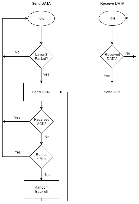
This example implements a data link layer based on the ALOHA random access protocol [ 2 ]. The following flow diagram shows how the ALOHA protocol transmits and receives data packets.

When the data link layer has a layer 3 packet to transmit, it starts a new session and sends the packet right away using a DATA packet. The algorithm waits for an acknowledgment (ACK) packet. If it does not receive an ACK before the timeout period, it backs off a random amount of time and sends the DATA packet again. If it fails to receive an ACK after a number of retries, it drops the packet. If the algorithm receives a new layer 3 packet during this session, the layer 3 packet is put in a first-in-first-out (FIFO) queue. If the FIFO queue is full, the packet is dropped.
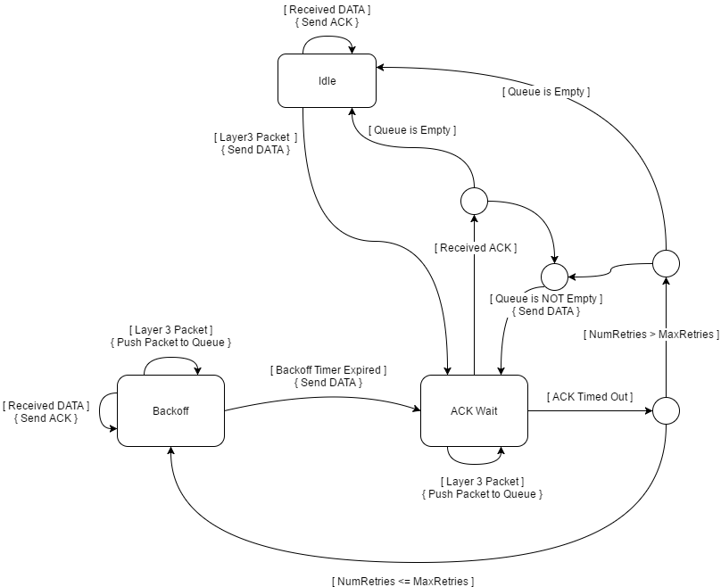
The algorithm is implemented in the helperPacketizedModemDataLinkLayer helper System object™. The helperPacketizedModemDataLinkLayer System object defines a state machine with three states: IDLE, ACK_WAIT, and BACKOFF. The following state machine describes how the data link layer algorithm is implemented in this object. Statements in brackets, [...], and curly braces, {...}, are conditions and actions, respectively. Small circles are passthrough states used to represent multiple conditions.

The original ALOHA protocol uses a hub/star topology. The uplink and downlink utilizes two separate frequency bands. The following example uses a mesh network topology where nodes transmit and receive using the same frequency band.
Modem Structure
The modem code structure executes these six main processing parts:
Source Controller
Message Generator
PHY Decoder
Data link layer
Message Parser
PHY Encoder
The data link layer processes outputs of the Message Generator and PHY Decoder, so it must run after those two operations. The Message Parser and PHY Encoder process outputs of the data link layer. This sequence ensures that the modem can receive packets and respond to them in the same time interval. The helperPacketizedModemNode object implements the modem.
Source Controller
The Source Controller generates an enable signal and a random destination address based on the user-selected packet arrival distribution.
Message Generator
The Message Generator starts creating layer 3 data packets when enabled by the source controller. The packets contain a digitized text message. If the message does not fit into one packet, the generator creates multiple packets. The packet structure is as follows:
To Address: 8 bits
From Address: 8 bits
Packet Number: 16 bits
Payload: M bits
PHY Decoder
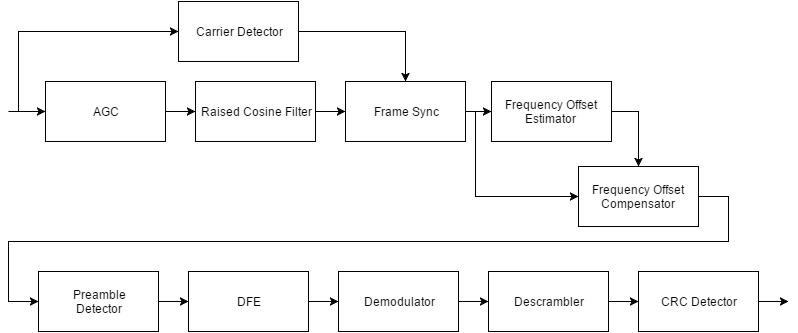
The PHY Decoder receives baseband I/Q samples and creates layer 2 packets. PHY Decoder corrects amplitude variations using an AGC, frequency offsets with a frequency offset estimator and compensator, and timing skews and multipath using a fractionally spaced decision feedback equalizer (DFE). The block diagram of the physical layer (layer 1) receiver is as follows:

When data payload size is set to 19530 bits, the total packet length of the modem is 39956 samples. The modem processes SamplesPerFrame samples, which is 2000 samples for this example, at each iteration. A smaller SamplesPerFrame results in smaller latency but increases the overhead of the modem algorithm. An increased overhead may increase the processing time such that the modem does not run in real-time anymore.
Data Link Layer
The data link layer provides a link between two neighboring nodes. It employs the ALOHA-based protocol described in the Data Link Layer (Layer 2) section. The packet structure contains these fields:
Type: 4 bits
Version: 2 bits
Reserved: 2 bits
To Address: 8 bits
From Address: 8 bits
Sequence Number: 8 bits
Time stamp: 32 bits
Payload: N ( = M+32) bits
The data link layer also collects these statistics:
Number of successful packet transfers, which is defined as the number of successfully received ACK packets
Average retries
Average round trip time in seconds
Number of dropped packets due to layer 3 packet queue being full
Number of dropped packets due to retries
Throughput defined as successful data delivery rate in bits per second
Average latency in seconds defined as the time between the generation of the layer 3 data packet and reception of it at the destination node
Message Parser
The message parser parses the received layer 2 payload and creates layer 3 packet. The message parser collects these statistics:
Number of received packets
Number of received duplicate packets
PHY Encoder
The PHY encoder creates physical layer packets by modulating the layer 2 packets into baseband I/Q samples. The packet structure is shown here.

The dummy symbols are used to train the AGC and for carrier detection. The synchronization symbols are a modulated PN-sequence. The header has these fields:
Payload length: 16 bits
CRC: 16 bits
This image shows the block diagram of the physical layer (layer 1) transmitter.

Channel Model
This example simulates a three-node network but any number of nodes can be simulated. The output of each node is passed to the channel simulator. The channel adds baseband signals from all three nodes after imposing these channel impairments:
Timing skew
Frequency offset
Rician multipath
AWGN
In addition to these impairments, the signals from neighboring nodes are applied a path loss of 20 dB, while the self-interference is added directly.

Run Using Radios
You can also run this example using radios instead of a simulated channel. The combination of an SDR hardware and a host computer that runs a MATLAB session comprises a node. The following steps show you how to set up a three-node network. This example uses USRP® B200 and B210 radios.
Connect a USRP® radio to host computer A, referred to as Node 1. Follow the instructions in Installation and Setup to install and setup your host computer for use with USRP® radios. Start a MATLAB session.
Set up Node 1 as a transmitter for initialization. The
helperPacketizedModemInitializeRadioinitializes the connected USRP® radio. RunhelperPacketizedModemInitializeRadio('tx', PLATFORM, ADDRESS, FC, RT), wherePLATFORMis the type of the USRP® radio,ADDRESSis the serial number or IP address,FCis the center frequency, andRTis run time in seconds. This example uses 915 MHz for the center frequency. Assuming that your radio is a B200 with serial number 'ABCDE', the function call will behelperPacketizedModemInitializeRadio('tx', 'B200', 'ABCDE', 915e6, 120). This function will run the transmitter for 120 seconds. If you need more time to finish the initialization, rerun the command with a longer run time.Repeat step 1 for a second radio and host computer and call this node Node 2.
Set up Node 2 as a receiver for initialization. Run
[CDT, MAXGAIN, RXGAIN] = helperPacketizedModemInitializeRadio('rx', PLATFORM, ADDRESS, FC, RT). Assuming that your radio is a B210 with serial number '12345', the function call will be[CDT1, MAXGAIN1, RXGAIN1] = helperPacketizedModemInitializeRadio('rx', 'B210', '12345', 915e6, 120). The function will run until it determines the best values for carrier detector threshold (CDT), maximum AGC gain (MAXGAIN), and radio receive gain (RXGAIN) or untilRTseconds have elapsed. If the initialization algorithm cannot determine suitable parameters, it may suggest increasing or decreasing the transmitter power and retrying the initialization.Run the same experiment with Node 1 as the receiver and Node 2 as the transmitter to determine best receiver parameters for Node 1. In most cases the channel should be dual and the parameters will be very close.
Repeat steps 1-5 for all other pairs of radios, that is Node 1 and Node 3, Node 3 and Node 2. Obtain
CDT,MAXGAIN, andRXGAINvalues for each node. If you get different values for the same node while initializing for different links, choose the maximum values forMAXGAINandRXGAIN, and minimum ofCDT.Start Node 1 by running the
helperPacketizedModemRadiohelper function. Use the commandhelperPacketizedModemRadio(P,RA,NA,DA,FC,CDT,MAXG,RGAIN,D), wherePis platform,RAis radio address,NAis node address,DAis destination address list,FCis center frequency,CDTis carrier detection threshold,MAXGis maximum AGC gain,RGAINis radio receiver gain, andDis duration. For example, run ashelperPacketizedModemRadio('B200','ABCDE',1,[2 3],915e6,CDT1,MAXGAIN1,RXGAIN1,120).Start Node 2 by running
helperPacketizedModemRadio('B210','12345',2,[1 3],915e6,CDT2,MAXGAIN2,RXGAIN2,120).Start Node 3 by running
helperPacketizedModemRadio('B200','A1B2C',3,[1 2],915e6,CDT3,MAXGAIN3,RXGAIN3,120).Once the session ends, each node prints out its statistics.
A three network setup operated for two hours. Each node generated packets at a rate of 0.2 packets/second according to a Poisson distribution. The nodes were placed approximately equal distance. One of the links had line-of-sight while other two did not. The following are the results collected on all three nodes. Since the round trip time of a DATA-ACK exchange using the B2xx radios connected over USB can be as high as 800 msec, the average round trip time of the network is greater than 3 sec. The algorithm minimizes packet loss and provides a fair access to the shared channel to all nodes.
Node 1:
 NumGeneratedPackets: 1440
 NumReceivedPackets: 1389
 AverageRetries: 0.533738
 AverageRoundTripTime: 3.725093
 NumDroppedPackets: 95
 NumDroppedPackets (Max retries): 23
 Throughput: 5.242823e+03
Node 2:
 NumGeneratedPackets: 1440
 NumReceivedPackets: 1340
 AverageRetries: 0.473157
 AverageRoundTripTime: 3.290775
 NumDroppedPackets: 31
 NumDroppedPackets (Max retries): 9
 Throughput: 5.934772e+03
Node 3:
 NumGeneratedPackets: 1440
 NumReceivedPackets: 1385
 AverageRetries: 0.516129
 AverageRoundTripTime: 3.558408
 NumDroppedPackets: 107
 NumDroppedPackets (Max retries): 29
 Throughput: 5.488410e+03
Discussions
The simulation code from previous sections and the helperPacketizedModemRadio helper function both utilize the helperPacketizedModemNode System object to implement the modem node. In this example, the same code is used to evaluate a system, first using a simulated channel, then using SDR hardware and over-the-air channels.
Even though the code using simulated channels is time-based, the modem node object could be used to run an event-based simulation. This example does not provide an event-based simulation kernel.
Further Exploration
You can vary these parameters to investigate their effect on data link layer performance:
PacketArrivalRateACKTimeOutMaxBackoffTimeMaxDataRetriesQueueSize
You can also explore the helper functions for implementation details of the algorithms:
helperPacketizedModemNode.mhelperPacketizedSourceController.mhelperPacketizedModemMessageGenerator.mhelperPacketizedModemDataLinkLayer.mhelperPacketizedModemPHYEncoder.mhelperPacketizedModemPHYDecoder.mhelperPacketizedModemMessageParser.mhelperMultiUserChannel.m
You can examine the physical layer only performance using the PacketizedModemPhysicalLayerTxRxExample script.
Selected Bibliography
[1] Data Link Layer
[2] ALOHANet
Copyright Notice
Universal Software Radio Peripheral® and USRP® are trademarks of National Instruments® Corp.