M-DPSK Modulator Baseband
Modulate using M-ary differential phase shift keying method
Library
PM, in Digital Baseband sublibrary of Modulation
Description
The M-DPSK Modulator Baseband block modulates using the M-ary differential phase shift keying method. The output is a baseband representation of the modulated signal. The M-ary number parameter, M, is the number of possible output symbols that can immediately follow a given output symbol.
The input must be a discrete-time signal. For integer inputs, the block can accept the
data types int8, uint8, int16,
uint16, int32, uint32,
single, and double. For bit inputs, the block
can accept int8, uint8, int16,
uint16, int32, uint32,
boolean, single, and
double.
The input can be either bits or integers, which are binary-mapped or Gray-mapped into symbols.
This block accepts column vector input signals. For a bit input, the input width must be an integer multiple of the number of bits per symbol.
Integer-Valued Signals and Binary-Valued Signals
If you set the Input type parameter to
Integer, then valid input values are integers between
0 and M-1. In this case, the input can be either a scalar or a frame-based column
vector. If the first input is k1, then the modulated symbol
is
where θ represents the Phase rotation parameter. If a successive input is k, then the modulated symbol is
When you set the Input type parameter to Bit,
the block accepts binary-valued inputs that represent integers. The block collects
binary-valued signals into groups of K =
log2(M) bits, where K is the number of bits per symbol and
M is the modulation order. The input vector length must be an integer
multiple of K. In this configuration, the block accepts a group of
K bits and maps that group onto a symbol at the block output. The
block outputs one modulated symbol for each group of K bits.
The input can be a column vector with a length that is an integer multiple of K.
In binary input mode, the Constellation ordering parameter
indicates how the block maps a group of K input bits to a
corresponding phase difference. The Binary option uses
binary-coded integer mapping, while the Gray option uses
a Gray-coded assignment of phase differences. For example, the following table
indicates the assignment of phase difference to three-bit inputs, for both the
Binary and Gray options. θ
is the Phase rotation parameter. The phase difference is
between the previous symbol and the current symbol.
| Current Input | Binary-Coded Phase Difference | Gray-Coded Phase Difference |
|---|---|---|
| [0 0 0] | jθ | jθ |
| [0 0 1] | jθ + jπ/4 | jθ + jπ/4 |
| [0 1 0] | jθ + jπ2/4 | jθ + jπ3/4 |
| [0 1 1] | jθ + jπ3/4 | jθ + jπ2/4 |
| [1 0 0] | jθ + jπ4/4 | jθ + jπ7/4 |
| [1 0 1] | jθ + jπ5/4 | jθ + jπ6/4 |
| [1 1 0] | jθ + jπ6/4 | jθ + jπ4/4 |
| [1 1 1] | jθ + jπ7/4 | jθ + jπ5/4 |
For more details about the Binary and
Gray options, see the reference page for the M-PSK Modulator Baseband block. The signal constellation for that block
corresponds to the arrangement of phase differences for this block.
Dialog Box
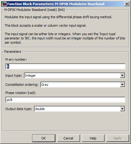
- M-ary number
The number of possible output symbols that can immediately follow a given output symbol.
- Input type
Indicates whether the input consists of integers or groups of bits. If this parameter is set to
Bit, then the M-ary number parameter must be 2K for some positive integer K.- Constellation ordering
Determines how the block maps each group of input bits to a corresponding integer.
- Phase rotation (rad)
The phase difference between the previous and current modulated symbols when the input is zero.
- Output data type
The output data type can be either
singleordouble. By default, the block sets this todouble.
Supported Data Types
| Port | Supported Data Types |
|---|---|
Input |
|
Output |
|
Pair Block
References
[1] Pawula, R. F., "On M-ary DPSK Transmission Over Terrestrial and Satellite Channels," IEEE Transactions on Communications, Vol. COM-32, July 1984, 752-761.
Extended Capabilities
Version History
Introduced before R2006a