Main Content

Data Mapper

Map integer symbols from one coding scheme to another

  • Data Mapper block

Libraries:
Communications Toolbox / Utility Blocks

Description

The Data Mapper block accepts integer inputs and maps them to integer outputs. The mapping types include: binary to Gray coded, Gray coded to binary, and user defined. Additionally, a pass through option is available.

Gray coding is an ordering of binary numbers such that all adjacent numbers differ by only one bit.

Examples

expand all

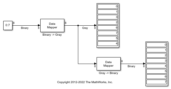
The doc_binary2gray model converts a binary sequence to a Gray-coded sequence and vice versa by using Data Mapper blocks.

Run the model.

The Display blocks show the binary-coded and Gray-coded sequence ordering.

Ports

Input

expand all

Input signal, specified as a scalar, vector, or matrix of integers. Elements of the input signal must be nonnegative values. The block truncates noninteger values to integer values. When the input is a matrix, the columns are treated as independent channels.

Data Types: double | single | int8 | int16 | int32 | uint8 | uint16 | uint32

Output

expand all

Output signal, returned as a scalar, column vector, or matrix. The dimensions of the output signal match those of the input signal.

Data Types: double | single | int8 | int16 | int32 | uint8 | uint16 | uint32

Parameters

expand all

To edit block parameters interactively, use the Property Inspector. From the Simulink® Toolstrip, on the Simulation tab, in the Prepare gallery, select Property Inspector.

Mapping mode, specified as Binary to Gray, Gray to Binary, User Defined, or Straight through. This table shows the mapping for the Binary to Gray and the Gray to Binary modes for input in the range [0, 7].

Binary to Gray ModeGray to Binary Mode
InputOutputInputOutput
0 0 (000) 0 (000) 0
1 1 (001) 1 (001) 1
2 3 (011) 2 (010) 3
3 2 (010) 3 (011) 2
4 6 (110) 4 (100) 7
5 7 (111) 5 (101) 6
6 5 (101) 6 (110) 4
7 4 (100) 7 (111) 5

When you select the User Defined mode, you can use any arbitrary mapping by providing a vector to specify the output ordering. When you select the Straight through mode, the output equals the input.

Symbol set size, specified as a positive integer. This parameter restricts the inputs and outputs to integers in the range [0, (M – 1)].

Mapping vector, specified as vector of nonnegative integers whose length equals the length of the input signal at the input port In. This parameter defines the relationship between the input and output integers. For example, the vector [1 5 0 4 2 3] defines the following mapping:

011520344253

Block Characteristics

Data Types

double | fixed point | integer | single

Multidimensional Signals

no

Variable-Size Signals

no

Extended Capabilities

C/C++ Code Generation
Generate C and C++ code using Simulink® Coder™.

Version History

Introduced before R2006a