Send and Receive CAN FD Messages on NVIDIA Jetson
R2026bThis example shows how to send and receive CAN flexible-data (FD) rate messages on NVIDIA® Jetson™ hardware. You connect to a Jetson hardware board, set up two CAN interfaces with loopback on the board, and deploy a Simulink® model that transmits and receives messages by using the CAN interfaces. You also use bit rate switching to send the data at a faster rate.
Prerequisites
To run this example, you must have:
The MATLAB® Coder™ Support Package for NVIDIA Jetson and NVIDIA DRIVE® Platforms.
An NVIDIA Jetson embedded platform. You must set up the Jetson hardware board by using the Hardware Setup tool.
An Ethernet crossover cable to connect the target board and host computer. If you connect the board to a local network, you do not need a cable.
The BusyBox tool installed on the board. This example uses the
busyboxcommand to set the pin mux settings on the board.Two CAN transceivers. This example uses two WaveShare SN65HVD230 CAN boards.
Connect to NVIDIA Hardware
Create a live hardware connection object by using the jetson function. When connecting to the target board for the first time, provide the host name or IP address, username, and password of the target board by using this syntax:
hwObj = jetson("jetson-deviceaddress","username","password");
If you call the jetson function without input arguments, MATLAB reuses the device address, username, and password from the last successful connection.
hwObj = jetson;
### Checking for CUDA availability on the target...
### Checking for 'nvcc' in the target system path...
### Checking for cuDNN library availability on the target...
### Checking for TensorRT library availability on the target...
### Checking for prerequisite libraries is complete.
### Gathering hardware details...
### Checking for third-party library availability on the target...
### Gathering hardware details is complete.
Board name              : NVIDIA Jetson AGX Orin Developer Kit
CUDA Version            : 11.4
cuDNN Version           : 8.6
TensorRT Version        : 8.5.2
GStreamer Version       : 1.16.3
V4L2 Version            : 1.18.0
SDL Version             : 1.2
OpenCV Version          : 4.5.4
Available Webcams       :
Available GPUs          : Orin
Available Digital Pins  : 7  11  12  13  15  16  18  19  21  22  23  24  26  29  31  32  33  35  36  37  38  40
Set Up CAN Interface
This example sends and receive CAN messages by using two CAN transceivers connected to the target hardware. Connect the CAN transceivers to the CAN0 and CAN1 interfaces of the board, and connect the two CAN transceivers to each other in loopback. This diagram shows an example connection for two CAN transceivers and an NVIDIA Jetson AGX Orin™ 40-pin header.
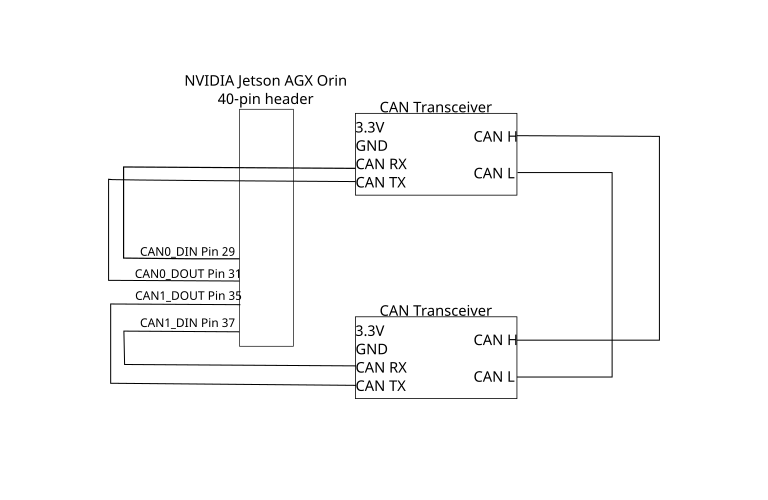
To set up the CAN interface, update the pin mux register settings and load the CAN modules by using shell commands. For more information about setting up your board, see Controller Area Network (CAN) on the NVIDIA website.
To open a shell on the target hardware, use the openShell function in the MATLAB Command Window:
openShell(hwObj);
Update the pin settings on the board by using the busybox tool. The pin addresses and values you use depend on the type of hardware board. This code updates the pin settings for an AGX Orin hardware board:
busybox devmem 0x0c303018 w 0xc458
busybox devmem 0x0c303010 w 0xc400
busybox devmem 0x0c303008 w 0xc458
busybox devmem 0x0c303000 w 0xc400
From the shell on the Jetson target, load the CAN modules.
modprobe can
modprobe can_raw
modprobe mttcan
Open and Configure the Model
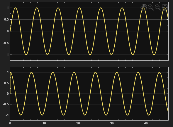
Open the Simulink model. The model contains a CAN FD Transmit block that writes to the CAN0 interface and a CAN FD Receive block that reads from the CAN1 interface. The model creates two signals of the double data type that represent a sine wave and a cosine wave. Two Byte Pack blocks convert the signals to uint8 vectors, and the CAN FD Transmit block sends a combined, 16-element uint8 vector. The CAN FD Receive block receives the 16-byte messages, and a Byte Unpack block converts the received data back to two double type signals.
open_system("CANFDSendAndReceive");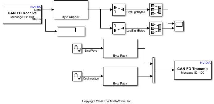
To configure the model for CAN FD communication, configure the CAN FD Transmit and CAN FD Receive blocks.
Configure the CAN FD Transmit Block
To prepare the CAN FD Transmit block for CAN FD communication, configure the block to set up and use the CAN0 interface, send 16-byte messages, and use bit rate switching. Set the data rate that the block uses to transmit the CAN data.
Double-click the CAN FD Transmit block. In the block parameters dialog box, follow these steps:
Set the CAN interface parameter to
can0. Set the Message ID parameter to100.Select the Set up CAN interface parameter.
To send 16-byte messages, set the Message Length parameter to
16.Select the Enable bit rate switching parameter. When you select this parameter, the block enables the bit-rate switching (BRS) bit in the CAN frames that it transmits. If the message from the
CAN FD Transmitblock wins arbitration, the block sends the data by using a separate, faster data rate.
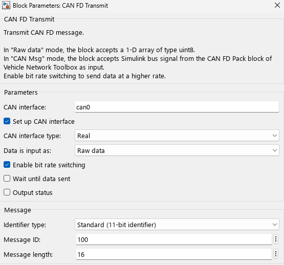
Alternatively, use the set_param function to set the block parameters.
transmitBlockPath = "CANFDSendAndReceive/CAN FD Transmit";
set_param(transmitBlockPath,DeviceID="can0");
set_param(transmitBlockPath,MessageId="100");
set_param(transmitBlockPath,SetupCAN="on");
set_param(transmitBlockPath,MsgLengthFD="16");
set_param(transmitBlockPath,EnableBitRateSwitching="on");
To set the data rate that the CAN FD Transmit block uses, set the CAN Data Bitrate (kBit/s) model configuration parameter. When the CAN FD Transmit block sets up the CAN0 interface, the block sets the data rate for CAN0 to the value of the CAN Data Bitrate (kBit/s) parameter.
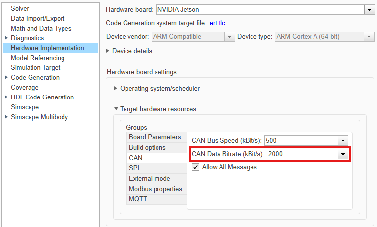
If you clear the Set up CAN interface block parameter in the CAN FD Transmit block, you must set up the CAN interface manually by using the ip link set shell command. In this case, the CAN interface uses the data rate that you specify when you set up the interface.
Configure the CAN FD Receive Block
To prepare the CAN FD Receive block, configure the block to set up and receive 16-byte messages on the CAN1 interface.
Double-click the CAN FD Receive block. In the block parameters dialog box, follow these steps:
Set the CAN interface parameter to
can1.Select the Set up CAN interface parameter.
To receive 16-byte messages, set the Message Length parameter to
16.
Alternatively, use the set_param function to set the block parameters.
receiveBlockPath = "CANFDSendAndReceive/CAN FD Receive";
set_param(receiveBlockPath,DeviceID="can1");
set_param(receiveBlockPath,SetupCAN="on");
set_param(receiveBlockPath,MsgLengthFD="16");
Run the Model in External Mode
On the Simulink Toolstrip, in the Hardware tab, select Monitor & Tune. Simulink generates code from the model and deploys the application to the hardware board. At each time step, the CAN FD Transmit block sends a CAN FD frame that contains a 16-element uint8 vector. The Scope block shows that the CAN1 interface receives the data for both waves.
See Also
CAN FD Receive | CAN FD Transmit | Byte Pack (Embedded Coder) | Byte Unpack (Embedded Coder)

