Design Wideband Cellular Base Station Antenna with Parasitic Elements
This example shows how to design a custom antenna with parasitic elements for cellular base station applications. Specifically, it shows how to create a model of a dipole antenna with additional parasitic elements to enhance its directivity and bandwidth. This example is particularly useful for engineers and researchers working on antenna design and looking to explore the effects of parasitic elements on antenna performance.
Define Antenna Dimensions
Initialize the dimensions of the dipole antenna and the parasitic elements. These dimensions are crucial for determining the antenna's operational frequency and characteristics.
% Antenna dimensions
l = 72e-3; % length of dipole
h = 45e-3; % vertical length
t = 0.814e-3; % thickness of vertical substrate
dip_wid = 2e-3; % dipole width
len_wid = 150e-3; % ground length and width
Create Dipole and Parasitic Elements
Use the dimensions defined in the previous section to create the geometry of the dipole antenna and the parasitic elements. The shape.Rectangle function allows you to define rectangular shapes, which you then manipulate to create the desired antenna structure.
Create main dipole elements.
rec1 = shape.Rectangle(Center=[6e-3 0],Length=10e-3,Width=45e-3);
[~] = translate(rec1,[0 0 -t/2]);
[~] = rotateX(rec1,90);

dipole1 = shape.Rectangle(Center=[23.5e-3 11.5e-3],Length=25e-3,Width=2e-3);
[~] = translate(dipole1,[0 0 -t/2]);
[~] = rotateX(dipole1,90);
Repeat for the second set of dipole elements.
rec2 = shape.Rectangle(Center=[-6e-3 0],Length=10e-3,Width=45e-3);
[~] = translate(rec2,[0 0 -t/2]);
[~] = rotateX(rec2,90);

dipole2 = shape.Rectangle(Center=[-23.5e-3 11.5e-3],Length=25e-3,Width=2e-3);
[~] = translate(dipole2,[0 0 -t/2]);
[~] = rotateX(dipole2,90);

shape1 = rec1 + dipole1 + rec2 + dipole2;
Create parasitic elements.
para_h = 33e-3;  % Parasitic element length
para_w = 2e-3;    % Parasitic element width
x1 = l/2;
x2 = (l/2) - 2e-3; % Parasitic element position

y = -(h/2) + 1e-3;   % Lower coordinate
k = y + para_h;      % Upper coordinate
x_cen = (x1 + x2)/2; % x-coordinate of center
y_cen = (y + k)/2;   % y-coordinate of center

parasitic1 = shape.Rectangle(Center=[x_cen y_cen],Length=para_w,Width=para_h);
[~] = translate(parasitic1,[0 0 t/2]);
[~] = rotateX(parasitic1,90);

parasitic2 = shape.Rectangle(Center=[-x_cen y_cen],Length=para_w,Width=para_h);
[~] = translate(parasitic2,[0 0 t/2]);
[~] = rotateX(parasitic2,90);
para = parasitic1 + parasitic2;
Create Feed line
Define feed line dimensions.
feed_h1 = 18.27e-3; % Vertical length
feed_h2 = 8.25e-3; % Second vertical length
feed_l = 15.9e-3;  % Horizontal length
f_w = 1.8e-3;  % Feed line width
mid_wid = 0.5e-3;  % Mid-line width
Use shape.Rectangle to create feed line.
f1 = shape.Rectangle(Center=[(-8.8e-3-8.8e-3+f_w)/2 (-h/2-h/2+feed_h1)/2],Length=1.8e-3,Width=18.27e-3);
[~] = translate(f1,[0 0 t/2]);
[~] = rotateX(f1,90);

f2 = shape.Rectangle(Center=[(-8.8e-3+feed_l-8.8e-3+feed_l-2e-3)/2 (-h/2+feed_h1-h/2+feed_h1-feed_h2)/2],Length=2e-3,Width=8.25e-3);
[~] = translate(f2,[0 0 t/2]);
[~] = rotateX(f2,90);

f3 = shape.Rectangle(Center=[(-8.8e-3-8.8e-3+feed_l)/2 (-h/2+feed_h1-h/2+feed_h1+2e-3)/2],Length=15.9e-3,Width=2e-3);
[~] = translate(f3,[0 0 t/2]);
[~] = rotateX(f3,90);

feedline = f1 + f2 + f3;
Create Antenna Shape
Combine the individual elements using Boolean addition to create the antenna structure. This process involves adding the dipole and parasitic elements.
shape1 = shape1 + feedline + para;
Define Ground Plane, Substrate, and Bounding box
A ground plane and substrate are essential for the antenna's performance. Define a ground plane, substrate, and bounding box for the antenna.
gnd = shape.Rectangle(Length=len_wid,Width=len_wid);
[~] = rotateZ(gnd,90);

[~] = translate(gnd,[0 0 round((-h/2)-(l/6000),4)]);
gnd_shape = add(gnd,shape1);
Create substrate shape.
substrate1 = shape.Box(Length=85e-3,Width=47e-3,Height=t,Dielectric="FR4",Color="r");
[~] = translate(substrate1,[0 1e-3 0]);
Create a bounding box of air to enclose the antenna. Defining this box is necessary because the mesher requires you to input a closed mesh.
Boundbox = shape.Box(Length=250e-3,Width=250e-3,Height=150e-3,Dielectric="Air",Color="b",Transparency=0.1);
sub1 = substrate1;
[~] = rotateX(sub1,90);
sub1 = sub1 + Boundbox;
gnd_diele_shape = addSubstrate(gnd_shape,sub1);
Create and Visualize Antenna
Use the createFeed function to add the feed. With the antenna structure defined, visualize it using the show function. Visualizing the antenna helps you verify the geometry before proceeding with the analysis.
ant = customAntenna(Shape=gnd_diele_shape);
[~] = createFeed(ant,[-7.9e-3,-t/2,(-h/2)],1);
figure
show(ant)
title("Wideband Cellular Basestation Antenna")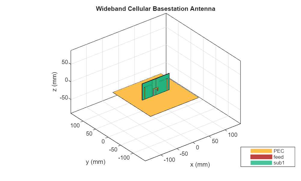
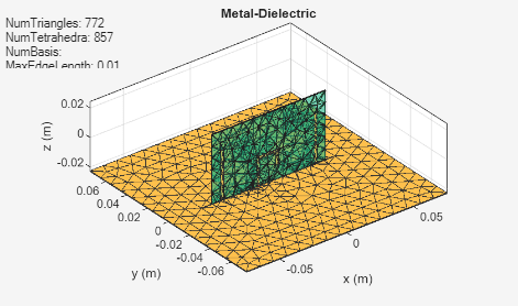
Analyze Antenna
Finally, analyze the antenna's performance by meshing it and calculating its radiation pattern and S-parameters over a specified frequency range.
Apply a mesh to the antenna.
mesh(ant,MaxEdgeLength=0.01)
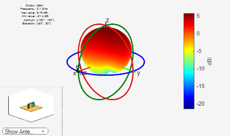
Plot the radiation pattern.
pattern(ant,2.1e9)
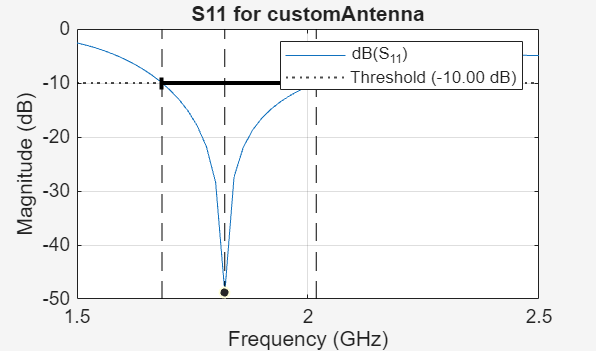
Calculate the S-parameters.
S = sparameters(ant,1.5e9:0.02e9:2.5e9);
rfplot(S)
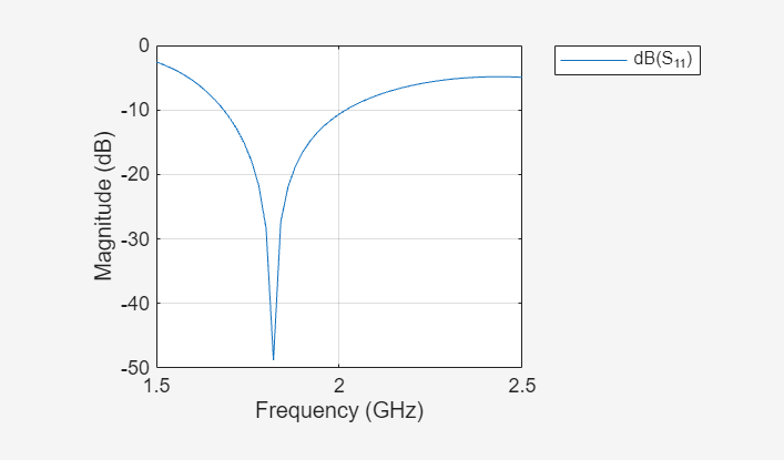
Use the bandwidth function to calculate the bandwidth below –10 dB.
bandwidth(ant,1.5e9:0.02e9:2.5e9);
Conclusion
The addition of two vertical parasitic elements to the base station antenna significantly improves the bandwidth by up to 350 MHz. The designed antenna has a maximum gain of around 5.7 dBi. The antenna is a promising candidate for a compact base station communication system.
References
[1] Luo, Yu, Qing-Xin Chu, and Jens Bornemann. 2017. "Enhancing Cross-Polarization Discrimination or Axial Ratio Beamwidth of Diagonally Dual or Circularly Polarized Base Station Antennas by Using Vertical Parasitic Elements." IET Microwaves, Antennas & Propagation 11. https://doi.org/10.1049/iet-map.2016.0928.
See Also
Objects
Functions
addSubstrate|bandwidth|createFeed|rotateX|rotateZ|translate
Topics
- Design and Analyze Perforated Horn Antenna for RF Applications
- Analysis of Basic Delta Loop Antenna over Ground
- Analyze Edge-Wall Slotted Waveguide Array Antenna for High-Frequency Applications
- Analysis of Ultrawideband Trident Inset-Fed Monopole Antenna with Conical Ground
- Design And Analyze Spherically Capped Biconical Antenna
- Feed Model
- Meshing
- Rotate Antennas and Arrays
- Port Analysis