Design Wideband MIMO PCB Antenna for Applications in 8 -12 GHz Band
This example shows how to design and analyze a compact microstrip patch antenna suitable for a variety of applications in the 8 -12 GHz frequency band. The design incorporates ground plane modifications and feed line adjustments to achieve desired performance characteristics across the specified frequency range. This example is particularly useful for engineers and researchers working on communication systems, radar, and RF sensing applications.
Design Antenna Dimensions
Define dimensions of the ground plane and main patch. The ground plane acts as a reflector for the patch antenna.
gp_L = 19e-3;
gp_W = 9.75e-3;
patch_L = 13e-3;
patch_W = 14e-3;
Create Patch And Feed Design
This section covers the design of the feed mechanism and the main radiating patch, crucial for efficient antenna performance. Use the antenna.Rectangle and antenna.Polygon objects to create radiating patch and feed line structure. The design of these structures is crucial for efficient antenna performance.
p = antenna.Rectangle(Center=[0 0],Length=patch_L,Width=patch_W);
feed = antenna.Rectangle(Center=[0 -11.75e-3],Length=2.6e-3,Width=9.5e-3);
a = antenna.Polygon(Vertices=[-6.5e-3 7e-3 0; -1.8e-3 7e-3 0; -6.5e-3 2.6e-3 0]);
b = antenna.Polygon(Vertices=[-1.3e-3 -7e-3 0; -6.5e-3 -7e-3 0; -6.5e-3 -2.6e-3 0]);
c = antenna.Polygon(Vertices=[6.5e-3 7e-3 0; 1.8e-3 7e-3 0; 6.5e-3 2.6e-3 0]);
d = antenna.Polygon(Vertices=[6.5e-3 -2.6e-3 0; 6.5e-3 -7e-3 0; 1.3e-3 -7e-3 0]);
t = antenna.Rectangle(Center=[0 1.75e-3],Length=4e-3,Width=12e-3);
x = p + feed - a - b - c - d - t;
figure(1);
show(x)
title("Patch Structure");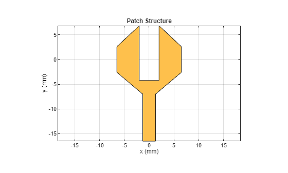
Defected Ground Structure
Modify the ground plane to create a defected ground structure (DGS), which helps in improving the bandwidth and impedance matching.
g1 = antenna.Rectangle(Center=[0 -11.625e-3],Length=gp_L,Width=gp_W);
g2 = antenna.Rectangle(Center=[-7.6e-3 -11.625e-3 ],Length=3.8e-3,Width=9.75e-3);
g3 = antenna.Rectangle(Center=[-4.875e-3 -16.125e-3],Length=6e-3,Width=0.75e-3);
g4 = antenna.Rectangle(Center=[7.5e-3 -16.125e-3],Length=12e-3,Width=0.75e-3);
g5 = antenna.Rectangle(Center=[0 -10.35e-3],Length=2.6e-3,Width=7.2e-3);
g6 = antenna.Rectangle(Center=[0 -2.55e-3],Length=9.5e-3,Width=6e-3);

gd = g1 - g2 - g3 - g4 - g5 + g6;
figure(2)
show(gd)
title("Ground Structure")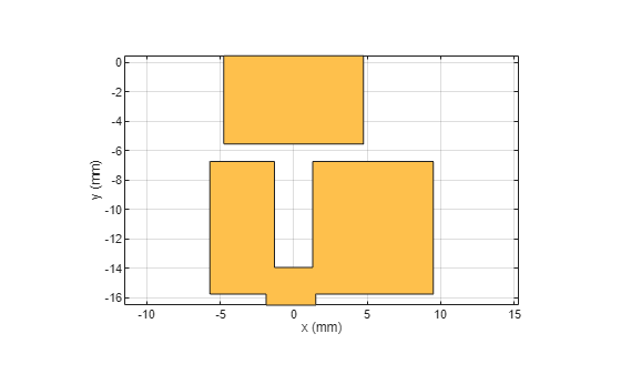
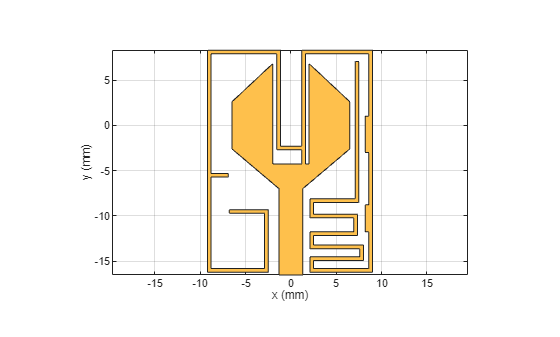
Trace and Stub Configuration
Create traces and stubs that form the radiating element and matching network of the antenna, respectively.
%E-shaped Stub
s1 = antenna.Rectangle(Center=[1.4e-3 2.025e-3],Length=0.4e-3,Width=12.55e-3);
s2 = antenna.Rectangle(Center=[5.1e-3 8.1e-3],Length=7.8e-3,Width=0.4e-3);
s3 = antenna.Rectangle(Center=[8.8e-3 -3.95e-3],Length=0.4e-3,Width=24.5e-3);
s4 = antenna.Rectangle(Center=[5.55e-3 -16.0e-3],Length=6.9e-3,Width=0.4e-3);
s5 = antenna.Rectangle(Center=[2.3e-3 -15.35e-3],Length=0.4e-3,Width=1.7e-3);
s6 = antenna.Rectangle(Center=[5.25e-3 -14.7e-3],Length=5.51e-3,Width=0.4e-3);
s7 = antenna.Rectangle(Center=[7.8e-3 -14.05e-3],Length=0.4e-3,Width=1.7e-3);
s8 = antenna.Rectangle(Center=[4.85e-3 -13.4e-3],Length=5.5e-3,Width=0.4e-3);
s9 = antenna.Rectangle(Center=[2.3e-3 -12.675e-3],Length=0.4e-3,Width=1.85e-3);
s10 = antenna.Rectangle(Center=[4.9e-3 -11.95e-3],Length=4.9e-3,Width=0.4e-3);
s11 = antenna.Rectangle(Center=[7.15e-3 -10.975e-3],Length=0.4e-3,Width=2.35e-3);
s12 = antenna.Rectangle(Center=[4.55e-3 -10e-3],Length=4.9e-3,Width=0.4e-3);
s13 = antenna.Rectangle(Center=[2.3e-3 -9.15e-3],Length=0.4e-3,Width=2.1e-3);
s14 = antenna.Rectangle(Center=[4.8e-3 -8.3e-3],Length=5.4e-3,Width=0.4e-3);
s15 = antenna.Rectangle(Center=[7.3e-3 -0.55e-3],Length=0.4e-3,Width=15.2e-3);
x1 = antenna.Rectangle(Center=[8.4e-3,-1e-3],Length=0.4e-3,Width=4e-3);
x2 = antenna.Rectangle(Center=[8.4e-3,-10.25e-3],Length=0.4e-3,Width=3e-3);

%G-shaped Stub
l1 = antenna.Rectangle(Center=[1.4e-3 -3.275e-3],Length=0.4e-3,Width=1.95e-3);
l2 = antenna.Rectangle(Center=[0.225e-3 -2.5e-3],Length=2.75e-3,Width=0.4e-3);
l3 = antenna.Rectangle(Center=[-1.35e-3 2.6e-3],Length=0.4e-3,Width=10.6e-3);
l4 = antenna.Rectangle(Center=[-5.175e-3 8.1e-3],Length=8.05e-3,Width=0.4e-3);
l5 = antenna.Rectangle(Center=[-9e-3 -3.9e-3],Length=0.4e-3,Width=24.4e-3);
l6 = antenna.Rectangle(Center=[-7.85e-3 -5.5e-3],Length=1.9e-3,Width=0.4e-3);
l7 = antenna.Rectangle(Center=[-5.85e-3 -16e-3],Length=6.7e-3,Width=0.4e-3);
l8 = antenna.Rectangle(Center=[-2.7e-3 -12.95e-3],Length=0.4e-3,Width=6.5e-3);
l9 = antenna.Rectangle(Center=[-4.65e-3 -9.5e-3],Length=4.3e-3,Width=0.4e-3);

%Radiating Patch with Stubs
o = x + l1 + l2 + l3 + l4 + l5 + l6 + l7 + l8 + l9 + x1 + x2 + s1 + s2 + s3 +s4 + s5 + s6 + s7 + s8 + s9 + s10 + s11 + s12 + s13 + s14 + s15;
figure(3)
show(o)
Place four ports of the MIMO orthogonal to each other in the top layer.
k = translate(o,[-18.6e-3,-11.5e-3,0]);
f1 = x + s1 + s2 + s3 + s4 + s5 + s6 + s7 + s8 + s9 + s10 + s11 + s12 + s13 + s14 + s15 + l1 + l2+ l3 +l4 + l5 + l6 + l7 + l8 + l9 + x1 + x2;
A1 = rotateZ(f1,90);
A = translate(A1,[11.5e-3,-18.6e-3,0]);
f2 = x + s1 + s2 + s3 + s4 + s5 + s6 + s7 + s8 + s9 + s10 + s11 + s12 + s13 + s14 + s15 + l1 + l2 + l3 + l4 + l5 + l6 + l7 + l8 + l9 + x1 + x2;
m1 = mirrorX(f2);
B = translate(m1,[18.6e-3,11.5e-3,0]);
f3 = x + s1 + s2 + s3 + s4 + s5 + s6 + s7 + s8 + s9 + s10 + s11 + s12 + s13 + s14 + s15 + l1 + l2 + l3 + l4 + l5 + l6 + l7 + l8+  l9 + x1 + x2;
m2 = mirrorX(f3);
C1 = rotateZ(m2,90);
C = translate(C1,[-11.5e-3,18.6e-3,0]);
patch = k + A + B + C;
figure(4);
show(patch)
title("Total Patch Structure");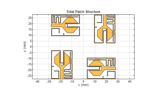
Place the individual ground planes of the MIMO orthogonal to each other.
r1 = mirrorY(gd);
r2 = translate(r1,[-18.5e-3,-11.5e-3,0]);
gd1 = g1 - g2 - g3 - g4 - g5 + g6;
r3 = mirrorY(gd1);
r4 = rotateZ(r3,90);
r5 = translate(r3,[11.5e-3,-18.5e-3,0]);
gd2 = g1 - g2 - g3 - g4 - g5 + g6;
r6 = rotateZ(gd2,180);
r7 = translate(r6,[18.5e-3,11.5e-3,0]);
gd3 = g1 - g2 - g3 - g4 -g5 + g6;
r8 = rotateZ(gd3,270);
r9 = translate(r8,[-11.5e-3,18.5e-3,0]);
ground = r2 + r5 + r7 + r9;
figure(5);
show(ground);
title("Antenna Ground Layer");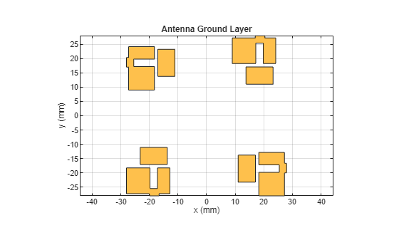
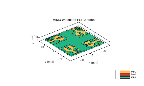
Create PCB Antenna
Use the pcbStack object to create PCB antenna from the top and ground layers created in previous steps.
h = 1.6e-3;
d1 = dielectric(Name="FR4",EpsilonR=4.4,LossTangent=0.0260,Thickness=h);
ps = pcbStack;
ps.BoardThickness = h;
r1bottom = antenna.Rectangle(Center=[0 0],Length=56e-3,Width=56e-3);
ps.BoardShape = r1bottom;
ps.Layers = {patch,d1,ground};
fx1 = -18.5e-3;
fy1 = -28e-3;
fx2 = 28e-3;
fy2 = -18.75e-3;
fx3 = 18.75e-3;
fy3 = 28e-3;
fx4 = -28e-3;
fy4 = 18.75e-3;
ps.FeedLocations = [fx1 fy1 1 3;fx2 fy2 1 3;fx3 fy3 1 3;fx4 fy4 1 3];
ps.FeedDiameter = (2.6e-3)/4;
ps.FeedVoltage = [1 1 1 1];
ps.FeedPhase = [0 0 0 0];
figure(6);
show(ps);
title("Wideband MIMO PCB Antenna");
lambda = 3e8/(12e9*sqrt(4.4));
Analyze PCB antenna
Load MAT-file containing S-parameters over the 8 - 12 GHz frequency band.
load('dspar_MIMO.mat');
rfplot(spar,1,1);
hold on;
rfplot(spar,2,2);
hold on;
rfplot(spar,3,3);
hold on
rfplot(spar,4,4);
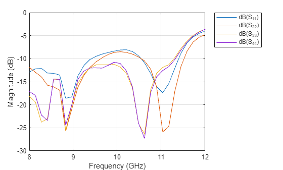
Conclusion
This designed antenna operates over the 8 to 12 GHz bandwidth with omnidirectional characteristics. Stubs are integrated into the UWB monopole antenna element to achieve wideband. The proposed MIMO antenna could be helpful for GPS, RFID/Bluetooth/Wi-Fi, and V2V communications.
See Also
Objects
Functions
Topics
- Design Series-Fed Patch Antenna Array for 5G Base Station
- PCB Antenna for USB Dongle and BLE Applications
- Design and Analysis of Diamond-Shaped PCB Antenna for Ultra-Wideband Applications
- Design, Analyze, and Prototype 2-by-2 Patch Antenna Array
- Design S-Band Monopulse Tracking Radar Antenna
- Modeling and Analysis of 5G NR FR1 Ultra-Wideband Antenna
- Board Thickness versus Dielectric Thickness in PCB