Explore the NASA HL-20 Model
Introduction
This section introduces a NASA HL-20 lifting body airframe model that uses blocks from the Aerospace Blockset™ software to simulate the airframe of a NASA HL-20 lifting body, in conjunction with other Simulink® blocks.
The model simulates the NASA HL-20 lifting body airframe approach and landing flight phases using an automatic-landing controller.
For more information on this model, see NASA HL-20 Lifting Body Airframe.
What This Example Illustrates
The NASA HL-20 lifting body airframe example illustrates the following features of the blockset:
Representing bodies and their degrees of freedom with the Equations of Motion library blocks
Using the Aerospace Blockset blocks with other Simulink blocks
Feeding Simulink signals to and from Aerospace Blockset blocks with Actuator and Sensor blocks
Encapsulating groups of blocks into subsystems
Visualizing an aircraft with Simulink 3D Animation™ and Aerospace Blockset Flight Instrument library blocks.
Open the Example
To open the NASA HL-20 airframe example, type the command
openExample('aeroblk_HL20_UE'), at the MATLAB® command line. The model opens.
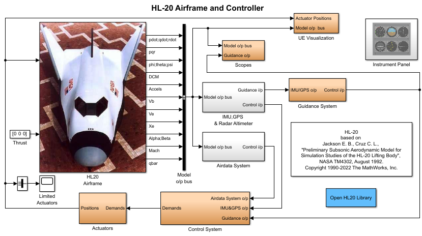
Key Subsystems
The model implements the airframe using the following subsystems:
The 6DOF (Euler Angles) subsystem implements the 6DOF (Euler Angles) block along with other Simulink blocks.
The Environment Models subsystem implements the WGS84 Gravity Model and COESA Atmosphere Model blocks. It also contains a Wind Models subsystem that implements a number of wind blocks.
The Alpha, Beta, Mach subsystem implements the Incidence, Sideslip, & Airspeed, Mach Number, and Dynamic Pressure blocks. These blocks calculate aerodynamic coefficient values and lookup functionality.
The Forces and Moments subsystem implements the Aerodynamic Forces and Moments block. This subsystem calculates body forces and body moments.
The Aerodynamic Coefficients subsystem implements several subsystems to calculate six aerodynamic coefficients.
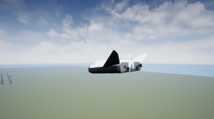
The UE Visualization subsystem implements the visualization of the aircraft simulation using Unreal Engine®.
The Instrument Panel contains flight instrument gauges.
NASA HL-20 Example
Running an example lets you observe the model simulation in real time. After you run the example, you can examine the resulting data in plots, graphs, and other visualization tools. To run this model, follow these steps:
If it is not already open, open the
aeroblk_HL20_UEexample.In the Simulink Editor, from the Simulation tab, select Run.
The simulation proceeds until the aircraft lands.
Plot that Measures Guidance Performance
Plot that Measures Altitude Accelerations Mach
Plot that Measures Inertial Position
Plot that Measures Demand Data Against Achieved Data

Modify the Model
You can adjust the airframe model settings and examine the effects on simulation performance. Here is one modification that you can try. It changes the point of view for the animation.
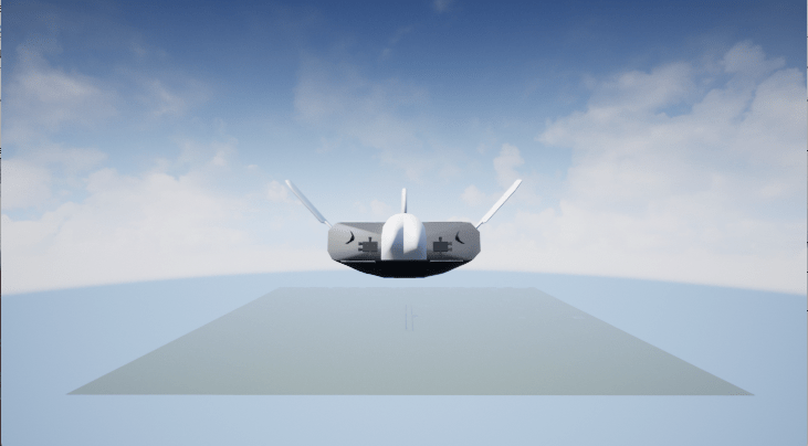
Change the Animation Point of View
By default, the airframe animation viewpoint is a rear viewpoint, which means the view tracks with the airframe flight path from the rear. You can change the animation point of view by selecting a number from 1 to 9 or 0. By default, 2 is the rear viewpoint.
Open the
aeroblk_HL20_UEmodel, and left-click the Simulation 3D Viewer window.From the keyboard, press 1.
The airframe view changes to a different viewpoint. This change does not persist. The next time you run the simulation, the Simulation 3D Viewer window shows the default viewpoint.
During simulation, experiment with different viewpoints to watch the animation from different perspectives.
See Also
6DOF (Euler Angles) | Incidence, Sideslip, & Airspeed | Mach Number | Dynamic Pressure | Aerodynamic Forces and Moments