Customize Scenes Using Simulink and Unreal Editor
After you install the Aerospace Blockset™ Interface for Unreal Engine® Projects support package as described in Install Support Package and Configure Environment, you can simulate in custom scenes simultaneously from both the Unreal® Editor and Simulink®. By using this co-simulation framework, you can add vehicles and sensors to a Simulink model and then run this simulation in your custom scene.
To use a project that you developed using a prior release of the support package, first migrate the project to be compatible with Unreal Engine 5.4. See Migrate Projects Developed Using Prior Support Packages.
Open Unreal Editor
Simulink will fail to establish a connection with the editor if you open the Unreal Editor outside MATLAB® or Simulink. To establish this connection, you must open your project from a Simulink model or use a MATLAB function.
The first time that you open the Unreal Editor, you might be asked to rebuild UnrealEditor DLL
files or the AutoVrtlEnv module. Click Yes to
rebuild these files or modules. The editor also prompts you that new plugins are
available. Click Manage Plugins and verify that the
MathWorks Interface plugin is installed. This plugin is the
MathWorksSimulation.uplugin file that you copied into your
Unreal Editor installation in Install Support Package and Configure Environment.
Messages about files with the name '_BuiltData' indicate missing
lighting data for the associated level. You should rebuild these levels' lighting before
shipping an executable
If you receive a warning that the lighting needs to be rebuilt, from the toolbar above
the editor window, select Build > Build Lighting Only. The editor issues this warning the first time you open a scene or when
you add new elements to a scene. To use the lighting that comes installed with
AutoVrtlEnv in Aerospace Blockset, see Use AutoVrtlEnv Project Lighting in Custom Scene.
Open Unreal Editor from Simulink
Open a Simulink model configured to simulate in the 3D environment. At a minimum, the model must contain a Simulation 3D Scene Configuration block.
In the Simulation 3D Scene Configuration block of this model, set the Scene source parameter to
Unreal Editor.In the Project parameter, browse for the project file that contains the scenes that you want to customize.
For example, this sample path specifies the
AutoVrtlEnvproject that comes installed with the Aerospace Blockset Interface for Unreal Engine Projects support package.This sample path specifies a custom project.C:\Local\AutoVrtlEnv\AutoVrtlEnv.uproject
Z:\UnrealProjects\myProject\myProject.uproject
Click Open Unreal Editor. The Unreal Editor opens and loads a scene from your project.
Open Unreal Editor Using Command-Line Function
To open the AutoVrtlEnv.uproject file that was copied from the
Aerospace Blockset Interface for Unreal Engine Projects support package, specify the path to where you copied
this project. For example, if you copied the AutoVrtlEnv.uproject
to C:/Local/AutoVrtlEnv, use this code:
path = fullfile('C:','Local','AutoVrtlEnv','AutoVrtlEnv.uproject');
editor = sim3d.Editor(path);
open(editor);
The editor opens the AutoVrtlEnv.uproject file.
To open your own project, use the same commands used to open the
AutoVrtlEnv.uproject file. Update the path
variable with the path to your .uproject file. For example, if
you have a project saved to the C:/Local folder, use this
code:
path = fullfile('C:','Local','myProject','myProject.uproject');
editor = sim3d.Editor(path);
open(editor);
Reparent Actor Blueprint
Note
If you are using a scene from the AutoVtrlEnv project that
comes installed with the Aerospace Blockset Interface for Unreal Engine Projects support package, skip this section. However, if you
create a new scene, then you must complete this section.
The first time that you open a custom scene from Simulink, you need to associate, or reparent, this project with the Sim3dLevelScriptActor level blueprint used in Aerospace Blockset. The level blueprint controls how objects interact with the 3D environment once they are placed in it. Simulink returns an error at the start of simulation if the project is not reparented. You must reparent each scene in a custom project separately.
To reparent the level blueprint, follow these steps:
In the Unreal Editor toolbar, click
 and select Open Level
Blueprint.
and select Open Level
Blueprint.In the Level Blueprint window, select File > Reparent Blueprint.
Click the Sim3dLevelScriptActor blueprint. If you do not see the Sim3dLevelScriptActor blueprint listed, use these steps to check that you have the
MathWorksSimulationplugin installed and enabled:In the Unreal Editor toolbar, select Edit > Plugins.
In the Plugins window, verify that the MathWorks Interface plugin is listed in the installed window. If the plugin is not already enabled, select the Enabled check box.
If you do not see the MathWorks Interface plugin in this window, repeat Configure Environment and reopen the editor from Simulink.
Close the editor and reopen it from Simulink.
Close the Level Blueprint window.
Custom Project Settings
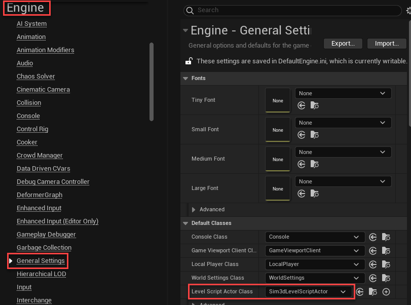
You can also reparent the level script actor class
for a custom project. To set the default class, from the Unreal Editor toolbar, select Edit > Project Settings > Engine > General Settings. Select Sim3dLevelScriptActor as the default class for
the level script actor class. Close Project Settings to save the default values and
reopen the editor from Simulink.
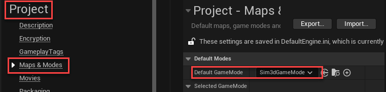
To use the default controls and features that come with the Mathworks
Interface plugin in a custom project, you must set the default game mode
of the project. In the Unreal Editor toolbar, select Edit > Project Settings > Project > Maps & Modes. Select Sim3dGameMode as the default game mode. Close
Project Settings to save the default values and reopen the editor from Simulink.
Create or Modify Scenes in Unreal Editor
After you open the editor, you can modify the scenes in your project or create new scenes.
Open Scene
In the Unreal Editor, scenes within a project are referred to as levels. Levels come in several types, and scenes have a level type of map.
To open a prebuilt scene from the AutoVrtlEnv.uproject file, in
the Content Drawer pane below the editor window, navigate to
the Content > Maps folder. Then, select the map that corresponds to the scene you want to
modify.
| Unreal Editor Map | Aerospace Blockset Scene |
|---|---|
Airport | Airport |
Apple Hill | Apple Hill |
Griffiss Airport | Griffiss Airport |
To open a scene within your own project, in the Content Drawer pane, navigate to the folder that contains your scenes.
Send Data to Scene
The Simulation 3D Message Get block retrieves data from the Unreal Engine 3D visualization environment. To use the block, you must configure scenes in the Unreal Engine environment to send data to the Simulink model.
For detailed information about using the block to send data to the scenes, see Get Started Communicating with the Unreal Engine Visualization Environment.
Receive Data from Scene
The Simulation 3D Message Set block sends data to the Unreal Engine 3D visualization environment. To use the block, you must configure scenes in the Unreal Engine environment to receive data from the Simulink model.
For detailed information about using the block to receive data from the scene, see Get Started Communicating with the Unreal Engine Visualization Environment.
Create New Scene
To create a new scene in your project, from the top-left menu of the editor, select File > New Level.
Alternatively, you can create a new scene from an existing one. This technique is
useful if you want to use one of the prebuilt scenes in the
AutoVtrlEnv project as a starting point for creating your own
scene. To save a version of the currently opened scene to your project, from the
top-left menu of the editor, select File > Save Current As. The new scene is saved to the same location as the existing
scene.
Add Assets to Scene
In the Unreal Editor, elements within a scene are referred to as assets. To add assets to a scene, you can browse or search for them in the Content Drawer pane at the bottom and drag them into the editor window.
When adding assets to a scene it is helpful to understand the origin and orientation of that scene’s coordinate system.
| Map | Coordinate Direction | Origin and Orientation |
|---|---|---|
Airport | X | Aligned with the runway, X = 3532.5 meters at the start of the runway. |
Y | Y = 0 at runway center. | |
Z | Z = 0 at ground level. | |
Griffiss Airport | X | Aligned with true North, X = 200.1 meters at the threshold of runway 33. |
Y | Aligned with true East, Y = -194.7 meters at the threshold of runway 33. | |
Z | Z matches actual elevation data, Z = 147.4 meters at ground level at the threshold of runway 33. |
When adding assets to a scene that is in the AutoVrtlEnv
project, you can choose from a library of driving-related assets. These assets are
built as static meshes and begin with the prefix
SM_. Search for these objects in the Content
Drawer pane.
For example, to add a hangar to a scene in the
AutoVrtlEnv project:
In the Content Browser pane at the bottom of the editor, navigate to the MathWorksAerospaceContent folder.
Expand the Environment > Hangar > Mesh folder, or search for
SM_Hangar. Drag the hangar from the Content Browser into the editing window. You can then change the position of the hangar in the editing window or on the Details pane on the right, in the Transform section.
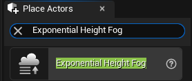
If you want to override the default weather or use enhanced fog conditions in the scene, add the Exponential Height Fog actor.
The Unreal Editor uses a left-hand Z-up coordinate system, where the Y-axis points to the right. The vehicle blocks in Aerospace Blockset uses a right-hand Z-down coordinate system, where the Y-axis points to the right. When positioning objects in a scene, keep this coordinate system difference in mind.
For more information on modifying scenes and adding assets, see Unreal Engine Documentation.
To migrate assets from the AutoVrtlEnv project into your own
project file, see the Unreal Engine documentation.
Use AutoVrtlEnv Project Lighting in Custom Scene
To use the lighting that comes installed with the
AutoVrtlEnv project in Aerospace Blockset Interface for Unreal Engine Projects, follow these steps.
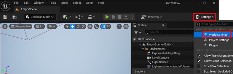
On the World Settings tab, clear Force no precomputed lighting.
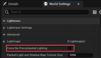
Tip
To display the World Settings tab, click Settings and select World Settings.
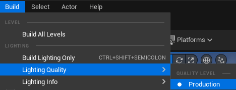
Under Build, select Lighting Quality > Production to rebuild the maps with production quality. Rebuilding complex maps can be time-intensive.
Run Simulation
Verify that the Simulink model and Unreal Editor are configured to co-simulate by running a test simulation.
In the Simulink model, click Run.
Because the source of the scenes is the project opened in the Unreal Editor, the simulation does not start. Instead, you must start the simulation from the editor.
Verify that the Diagnostic Viewer window in Simulink displays this message:
In the Simulation 3D Scene Configuration block, you set the scene
                        source to 'Unreal Editor'. In Unreal Editor, select 'Play' to view the
                        scene.
This message confirms that Simulink has instantiated vehicles and other assets in the Unreal Engine 3D environment.
In the Unreal Editor, click Play. The simulation runs in the scene currently open in the Unreal Editor. If your Simulink model contains vehicles, these vehicles drive through the scene that is open in the editor.
To control the view of the scene during simulation, in the Simulation 3D Scene Configuration block, select the vehicle name from the Scene view parameter. To change the scene view as the simulation runs, use the numeric keypad in the editor. The table shows the position of the camera displaying the scene, relative to the vehicle selected in the Scene view parameter.
To smoothly change the camera views, use these keyboard shortcuts.
| Keyboard Shortcut | Camera View | |
|---|---|---|
1 | Back left |
|
2 | Back | |
3 | Back right | |
4 | Left | |
5 | Internal | |
6 | Right | |
7 | Front left | |
8 | Front | |
9 | Front right | |
0 | Overhead | |
For additional camera controls, use these keyboard shortcuts.
| Keyboard Shortcut | Camera Control |
|---|---|
| Tab | Cycle the view between all vehicles in the scene. |
Scroll wheel | Control the camera distance from the vehicle. |
L | Toggle a camera lag effect on or off. When you enable the lag effect, the camera view includes:
This lag improves visualization of overall vehicle acceleration and rotation. |
| F | Toggle the free camera mode on or off. When you enable the free camera mode, you can use the pointer to change the pitch and yaw of the camera. This mode allows you to orbit the camera around the vehicle. |
To restart a simulation, click Run in the Simulink model, wait until the Diagnostic Viewer displays the confirmation message, and then click Play in the editor. If you click Play before starting the simulation in your model, the connection between Simulink and the Unreal Editor is not established, and the editor displays an empty scene.
If you are co-simulating a custom project, to enable the numeric keypad, copy the DefaultInput.ini file from the support package installation folder to your custom project folder. For example, copy DefaultInput.ini from:
C:\ProgramData\MATLAB\SupportPackages\<MATLABRelease>\toolbox\shared\sim3dprojects\spkg\project\AutoVrtlEnv\Config
C:\<yourproject>.project\Config
After tuning your custom scene based on simulation results, you can then package the scene into an executable. For more details, see Package Custom Scenes into Executable.
See Also
Simulation 3D Scene Configuration | sim3d.Editor