Custom
Customizable generic fixed-wing aircraft, including vertical takeoff and landing (VTOL) aircraft
Since R2022a
Description
Custom is one of the aircraft that you can use within the 3D simulation environment. It is the same skeleton as that used for the HL-20 aircraft. This environment is rendered using the Unreal Engine® from Epic Games®. This aircraft is designed to be customized with a user-supplied skeletal mesh. Two sample skeletal meshes are provided, one of which is shown in Views.
Simulating models in the 3D visualization environment requires Simulink® 3D Animation™.
To add this type of vehicle to the 3D simulation environment:
Add a Simulation 3D Aircraft block to your Simulink model.
In the Block Parameters dialog box, in the Aircraft Parameters tab, set the Type parameter to
Custom.Set the Path to air transport mesh parameter to either the sample mesh path or to your own air transport skeletal mesh path. The two sample skeletal mesh paths are
/MathWorksAerospaceContent/Vehicles/Aircraft/Custom/Mesh/SK_Aircraft.SK_and/MathWorksAerospaceContent/Vehicles/Aircraft/Custom/Mesh/SK_HL20.SK_HL20.On the Initial Values tab, set the Initial translation (in meters) and Initial rotation (in radians) parameters to an array size that matches the Custom aircraft, for example,
zeros(57,3).
Data for Aircraft Placement for Custom Mesh
The Custom sample mesh origin is near its center of mass, 1.163
meters above the bottoms of the tires. To correctly place the aircraft, consider using
these values.
Custom Airport Scene Placement
To place the Air Transport mesh in the
Airport scene resting on the pavement or other hard surface,
which is at a Z of 1 centimeter, use the following body
translation and rotation values.
| Body Motion Ports and Parameters | Value |
|---|---|
| Translation port and Initial translation parameter | [0, 0, -1.163] + [0, 0, -0.01] |
| Rotation port and Initial rotation parameter | [0, 0.01984, 0] |
Custom Aircraft Altitude Sensor
For the altitude sensor in the Simulation 3D Aircraft block, use these values.
| Parameter | Value |
|---|---|
| Body Z offset (m) | 1.163 |
| Front tire radius (m) | 0.203 |
| Left tire radius (m) | 0.203 |
| Right tire radius (m) | 0.203 |
Size
These are the unscaled sizes of the customizable generic fixed-wing aircraft mesh.
| Parameter | Value |
|---|---|
| Length (m) | 8.96 |
| Width (wingspan) (m) | 9.30 |
| Height (m) | 2.89 |
Data for Aircraft Placement for HL-20 Mesh
The HL-20 sample mesh origin is near its center of mass, 1.385
meters above the bottoms of the tires. To correctly place the aircraft, consider using
these values.
HL-20 Airport Scene Placement
To place the HL-20 mesh in the Airport scene
resting on the pavement or other hard surface, which is at a Z of
1 centimeter, use the following body translation and rotation values.
| Body Motion Ports and Parameters | Value |
|---|---|
| Translation port and Initial translation parameter | [0, 0, -1.385] + [0, 0, -0.01] |
| Rotation port and Initial rotation parameter | [0, 0.00901, 0] |
HL-20 Altitude Sensor
For the altitude sensor in the Simulation 3D Aircraft block, use these values.
| Parameter | Value |
|---|---|
| Body Z offset (m) | 1.385 |
| Front tire radius (m) | 0.1745 |
| Left tire radius (m) | 0.2208 |
| Right tire radius (m) | 0.2208 |
Size
These are the unscaled sizes of the HL-20 mesh.
| Parameter | Value |
|---|---|
| Length (m) | 7.27 |
| Width (wingspan) (m) | 5.60 |
| Height (m) | 2.73 |
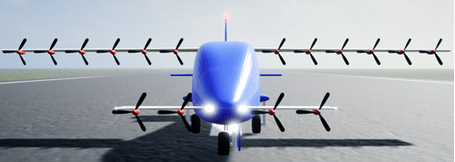
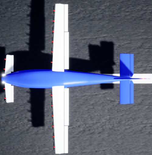
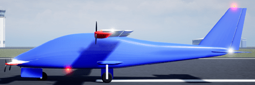
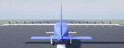
Views
This topic shows the views of the Custom aircraft. The Custom aircraft uses the same skeleton as the HL-20.
Lights and Skeleton
Lights
| Light | Bone | Location in SK_Aircraft Mesh |
|---|---|---|
| Left landing | LandingLight_L | Left of nose |
| Right landing | LandingLight_R | Right of nose |
| Taxi | NoseGear_Light | Nose gear strut |
| Red navigation | Wing1_RedNavLight | Left wingtip of WING1 |
| Green navigation | Wing1_GreenNavLight | Right wingtip of WING1 |
| Left wingtip strobe | Wing1_StrobeLight_L | Left wingtip of WING1 |
| Right wingtip strobe | Wing1_StrobeLight_R | Right wingtip of WING1 |
| Tail strobe | StrobeLight | Top of vertical stabilizer, pointing aft |
| Position #1 | PosititionLight1 | Left wingtip of WING2 |
| Position #2 | PosititionLight2 | Right wingtip of WING2 |
| Beacon #1 | BeaconLight1 | Top of vertical stabilizer |
| Beacon #2 | BeaconLight2 | Bottom of fuselage |
Skeleton
FixedWingEngine1Engine1_Prop
Engine2Engine2_Prop
Engine3Engine3_Prop
Engine4Engine4_Prop
Engine5Engine5_Prop
Engine6Engine6_Prop
Engine7Engine7_Prop
Engine8Engine8_Prop
Engine9Engine9_Prop
Engine10Engine10_Prop
Engine11Engine11_Prop
Engine12Engine12_Prop
Engine13Engine13_Prop
Engine14Engine14_Prop
Engine15Engine15_Prop
Engine16Engine16_Prop
Wing1Wing1_Aileron_LWing1_Aileron_RWing1_Flap_LWing1_Flap_RWing1_Spoiler_LWing1_Spoiler_RWing1_RedNavLightWing1_GreenNavLightWing1_StrobeLight_LWing1_StrobeLight_R
Wing2Wing2_Flap_LWing2_Flap_R
Rudder_LRudder_RHorizStabHorizStab_Elevator_LHorizStab_Elevator_R
NoseGearNoseGear_WheelNoseGear_Light
NoseGear_DoorMainGear_LMainGear_L_Wheel
MainGear_RMainGear_R_Wheel
MainGearDoor_LMainGearDoor_RLandingLight_LLandingLight_RBeaconLight1BeaconLight2StrobeLightPositionLight1PositionLight2
Version History
Introduced in R2022a