Faraday Accelerates SIP Development and Shrinks NAND Flash Controller ECC Engine Gate Count by 57% with Model-Based Design
“The Simulink environment is ideal for system-level architecture exploration. The simulations are 200 times faster than they were in our previous workflow—and Simulink models can be easily converted to C as well as to HDL code, which enables high scalability and reusability.”
Challenge
Solution
Results
- Simulations 200 times faster
- Throughput performance increased by 15%
- Gate count cut by 57%

Many integrated circuit manufacturers rely on silicon intellectual property (SIP) providers for system-on-a-chip (SoC) and application-specific integrated circuit (ASIC) design. For SIP designers, memory controllers represent an opportunity and a challenge: an opportunity because every microprocessor subsystem needs a memory controller; a challenge because memory controllers are complex designs that need continual enhancements to support a wide array of memory devices. SIP providers like Faraday Technology Corporation gain a competitive advantage if they reduce the gate count of their designs and shorten the development cycle for memory controllers and other modules, which ultimately lowers costs for their customers.
Faraday adopted MathWorks tools for Model-Based Design to accelerate SIP development, explore system-level design alternatives, and improve communication among engineers.
“Simulink is an excellent environment for integrating, simulating, and exploring design architectures,” says Ken Chen, ESL Methodology Manager at Faraday. “With Simulink we can perform cycle-based simulations up to 200 times faster than RTL simulations, which enables us to rapidly identify the best design configurations and get products to market faster.”

Challenge
In Faraday’s development workflow, engineers create design modules that they can rapidly configure and assemble into integrated system-level models. In the past, these modules were hand coded in SystemC, C++, or Verilog ®. When memory controller standards changed, the modules had to be recoded. Not only did hand coding take time, but the modules often had to be ported into another language for RTL simulation on proprietary simulation platforms.
When Faraday’s modules included discrete-time interactions, the simulations themselves were slow. For example, modules that control the flow of data for double data rate (DDR) memory or flash memory must employ a sophisticated communications protocol and manage large amounts of data. Simulating these modules proved so slow that to meet their deadline, Faraday had to limit design iterations and tests. With little time for optimization, the engineers designed for the worst-case scenario, which led to suboptimal designs with more gates—and a higher cost—than necessary.

Solution
Faraday engineers established a new workflow in which they use MATLAB®, Simulink®, and Stateflow® to model and simulate their system-level designs and Simulink Coder™ and HDL Coder™ to generate code from their models.
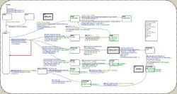
Working in Simulink and Stateflow, the engineers modeled multiple design modules, including finite state machines (FSMs) for the DDR and flash controllers. They performed extensive simulations in Simulink to ensure that the models were cycle accurate for a range of configurations. They used MATLAB to run statistical analysis on the models.
In the architecture design phase, Faraday engineers evaluated various combinations of modules and tried different parameter values. They used their simulation results to optimize and improve the designs. “Stateflow makes it easy for engineers to communicate complex controller designs in detail and at a level of abstraction that is easy to understand,” says Chen.
As a faster alternative to RTL simulation, Faraday engineers used Simulink Coder to generate C code from their model. This C code provides a programmer’s view of the design and can be integrated into many virtual platform solutions for software development and system-level architecture exploration.
In the implementation phase, instead of manually coding their design, Faraday engineers used HDL Coder to automatically generate HDL code from the same Simulink model for integration into their RTL simulation. This workflow has enabled Faraday to shorten their design process as they moved from architecture design to an FPGA-based prototype.
Faraday has completed the DDR and flash controller projects and delivered the SIP designs to their customer on schedule. The engineering team is positioned to accelerate development on future memory controller projects by reusing and adapting their existing models.

Results
- Simulations 200 times faster. Simulations of system-level models with Simulink and Stateflow were 200 times faster than comparable RTL simulations. As a result, Faraday completed more design iterations and quickly identified optimal parameters and configurations.
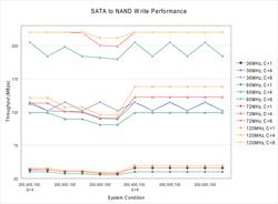
- Throughput performance increased by 15%. Simulink simulations revealed inefficiencies in the legacy design—specifically, in the arbiter and FIFO mechanism. Instead of redesigning the entire system, Faraday engineers focused on these components, quickly increasing throughput by 15%. By using Model-Based Design for the new DDR controller, Faraday improved system performance by more than 33%.
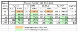
- Gate count cut by 57%. In the past, slow simulations and tight schedules limited design iterations and forced Faraday to design only for worst-case scenarios. Using MATLAB, Simulink, and Stateflow, they applied statistical error models and assessed system performance under both nominal and worst-case scenarios. They could then make informed tradeoff decisions that reduced the overall gate count on one project by 57%.