Reuse Custom Code in Stateflow Charts
You can integrate custom code written in C or C++ with Stateflow® charts in Simulink® models. By sharing data and functions between your custom code and your Stateflow chart, you can augment the capabilities of Stateflow and take advantage of your preexisting code.
Integrate Custom C Code in Stateflow Charts
This example shows how to use custom C code to define constants, variables, and functions that you can access in the charts in your model. For more information about integrating custom C++ code in your charts, see Access Custom C++ Code in Stateflow Charts.
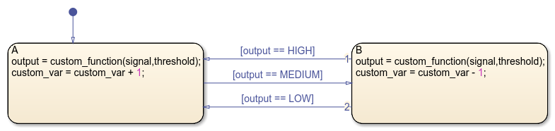
In this example, a Stateflow chart calls a custom code function named custom_function. This function reads the chart input signal and the local data threshold, compares their values, and returns one of three custom global constants named HIGH, MEDIUM, and LOW. The chart uses the value of the function to determine whether to transition to a new state after it increments or decrements the value of a custom variable named custom_var.
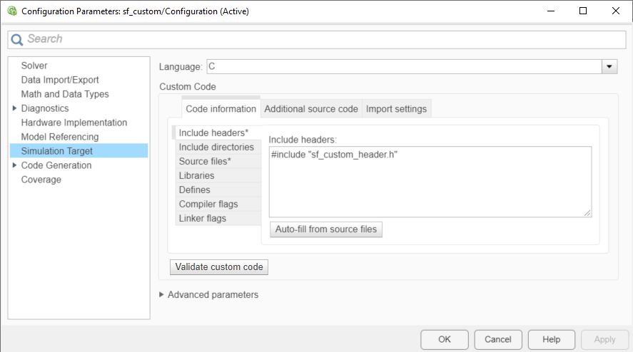
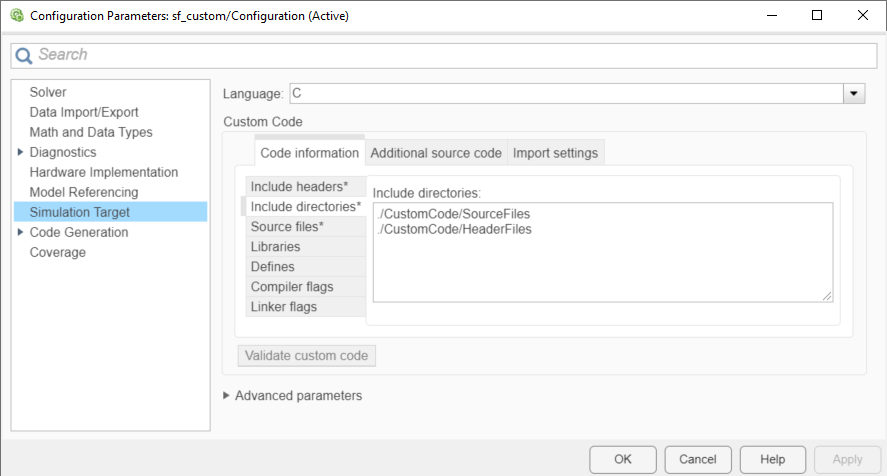
To see the custom code that this chart accesses, open the Configuration Parameters dialog box and, in the Simulation Target pane, select the Code Information tab.
The Include headers parameter contains an
#includestatement that specifies the header filesf_custom_header.h. This file contains the definitions of three static global constants and the declarations for the variablecustom_varand the functioncustom_function.The Source files parameter specifies the source file
sf_custom_source.c. This file sets the initial value ofcustom_varto zero and defines the functioncustom_function.
Both of these files are located in the same folder that contains the model. To access custom code files in a different folder, use relative path names. For more information, see Specify Relative Paths to Custom Code.
When you simulate the model, Stateflow compiles the source file and the chart into a single S-function MEX file. Because the custom definitions appear at the top of the generated machine header file sf_custom_header.h, every chart in the model can access the custom code during simulation.
Configure Custom Code
Specify Custom Code Settings for Simulation
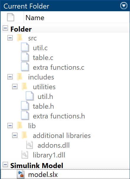
The examples for specifying C source, header, and library files are based on this folder structure.
To configure your model to access custom code during simulation, follow these steps.
Open the Configuration Parameters dialog box. For information on how to do this, see Set Configuration Parameters by Using the Dialog Box (Simulink).
In the Simulation Target pane, in the Code Information tab, specify these parameters:
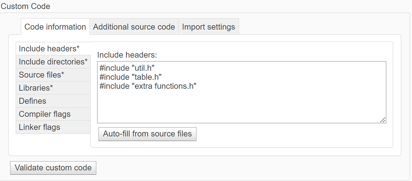
Include headers — Enter the code to include at the top of the generated
model.h#includeand#definestatements. When you include a custom header file, you must enclose the file name in double quotes. For more information, see Include headers (Simulink).Note
The code you specify in this parameter can include
externdeclarations of variables or functions, such asextern int xorextern void myfun(void). However, global variable or function definitions such asint xorvoid myfun(void)cause linking errors because the definitions appear multiple times in the source files of the generated code.
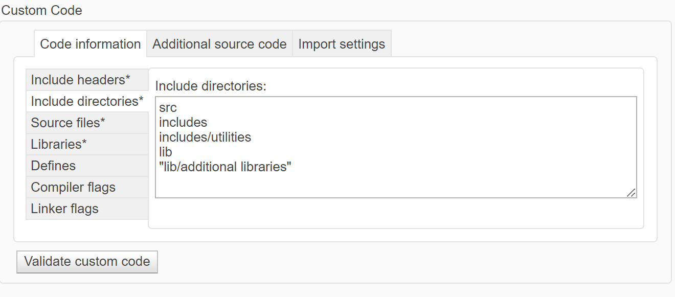
Include directories — Enter a list of the folder paths that contain custom header, source, and library files that you include either directly in the configuration parameters or indirectly in the compiled target. You can separate entries with newlines, spaces, or semicolons. For more information, see Include directories (Simulink).
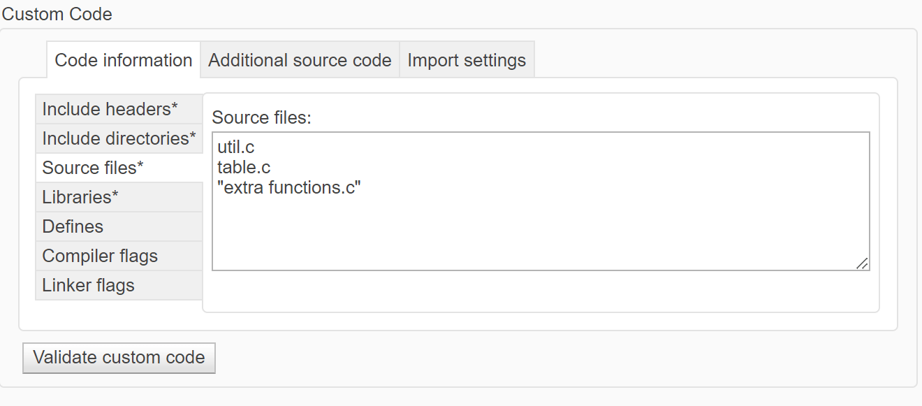
Source files — Enter a list of source files to compile and link into the target separated by newlines, spaces, or semicolons. For more information, see Source files (Simulink).
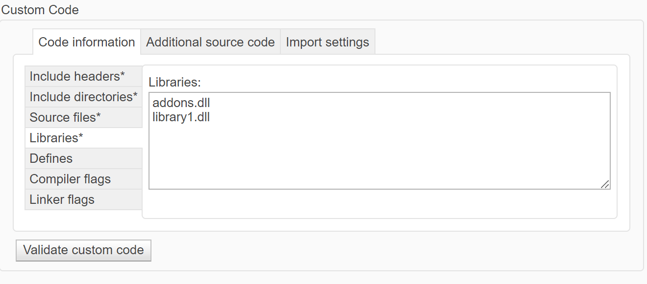
Libraries — Enter a list of static libraries that contain custom object code to link into the target, separated by newlines, spaces, or semicolons. For more information, see Libraries (Simulink).
Defines — Enter a space-separated list of preprocessor macro definitions to add to the generated code. For more information, see Defines (Simulink).
Compiler flags — Enter additional compiler flags to be added to the compiler command line when your custom code is compiled. For more information, see Compiler flags (Simulink).
Linker flags — Enter additional linker flags to be added to the linker command line when your custom code is linked. For more information, see Linker flags (Simulink).
Under Advanced parameters, check that Import custom code (Simulink) is selected. This parameter is enabled by default.
For information on setting simulation options by using the command-line API, see Set Configuration Parameters Programmatically.
Specify Custom Code Settings for Code Generation
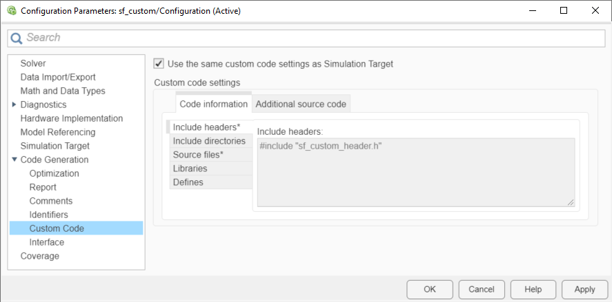
To configure your model to access custom code for code generation, use the Code Generation > Custom Code pane of the Configuration Parameters dialog box. You can use the same custom code settings for code generation that you use for simulation or use unique custom code settings.
To use the same custom code settings used for simulation, select Use the same custom code settings as Simulation Target. Specify the custom code settings in the Simulation Target pane as described in Specify Custom Code Settings for Simulation.
To use unique custom code settings, clear Use the same custom code settings as Simulation Target. In the Code Information tab, specify custom code settings for code generation. For descriptions of the parameters in this tab, see Specify Custom Code Settings for Simulation.
For more information, see Use the same custom code settings as Simulation Target (Simulink Coder) and Integrate External Code by Using Model Configuration Parameters (Simulink Coder).
Call Custom Code Functions in States and Transitions
You can call custom code functions from the actions of any state or transition or from other functions.
To call a custom code function, use the signature specified by the function declaration in your header file. Include an actual argument value for each formal argument in the function signature:
return_val = function_name(arg1,arg2,...)
Custom Code Configuration
If your model contains library charts, configure the custom code settings for each library model that contributes a chart to your model. For more information, see Configure Custom Code in Library Models.
Charts that use MATLAB® as the action language do not support
#definestatements in custom code. To share constants between your chart and your custom code, use static global constants instead of macros.Do not share fixed-point data between your custom code and your Stateflow chart.
Specify Relative Paths to Custom Code
When you update your model or start the simulation, the model searches for custom code files in these folders:
Current folder
Model folder (if this folder is different from the current folder)
Custom list of folders that you specify
All folders on the MATLAB search path, excluding the toolbox folders
You can specify the location of your custom code by using paths relative to one of these
folders. For instance, suppose that, in the previous example, you store the source and
header files for your custom code in the model folder subfolders
CustomCode/SourceFiles and CustomCode/HeaderFiles.
To access these files, use the Include directories parameter to specify
the relative paths of the subfolders.
Alternatively, you can use relative pathnames to specify the header and source files individually:
Under Include headers, enter this pathname.
#include "./CustomCode/HeaderFiles/sf_custom_code_constants_vars_fcns_hdr.h"Under Source files, enter this pathname.
./CustomCode/HeaderFiles/sf_custom_code_constants_vars_fcns_src.c
Guidelines for Relative Path Syntax
When you construct relative paths for custom code, follow these syntax guidelines:
Use a single period (
.) to indicate the starting point for the relative path.Use forward slashes (
/) or backward slashes (\) as file separators, regardless of the platform you are using.Enclose paths in double quotes (
"...") if they contain nonstandard path characters such as spaces or hyphens (-).Enclose expressions with dollar signs (
$...$) to:Evaluate the expressions in the MATLAB workspace. For example, suppose that
CustomCodeFolderis a variable that you define in the MATLAB workspace as"module1". If you specify your custom code files using the path name.\work\source\$CustomCodeFolder$, then the model searches for the custom code files in the folder.\work\source\module1.Use MATLAB functions that generate paths to your custom code files. The functions must be on the MATLAB search path.
For example, suppose that a function
myFolderFcnreturns the path to your custom code folder by running the commandfileparts(mfilename('fullpath')). If you specify a custom code file using the path name$myFolderFcn$/myCustomFile, then the model searches formyCustomFilein the folder returned bymyFolderFcn.
See Also
Topics
Select a Web Site
Choose a web site to get translated content where available and see local events and offers. Based on your location, we recommend that you select: United States.
You can also select a web site from the following list
Americas
- América Latina (Español)
- Canada (English)
- United States (English)
Europe
- Belgium (English)
- Denmark (English)
- Deutschland (Deutsch)
- España (Español)
- Finland (English)
- France (Français)
- Ireland (English)
- Italia (Italiano)
- Luxembourg (English)
- Netherlands (English)
- Norway (English)
- Österreich (Deutsch)
- Portugal (English)
- Sweden (English)
- Switzerland
- United Kingdom (English)