Real Time Target Emulation on NI USRP Radio
This example shows how to run a deployed target emulation algorithm continuously on an NI™ USRP™ radio FPGA using a second radio as pulse radar.
Associated Radar Target Emulation Examples
This example is one in a group of related examples that demonstrate how to use a radar target emulation design running on the FPGA of an NI USRP radio in different deployment scenarios. For more information, see Radar Target Emulation Applications Overview.
Introduction
In this example, you configure one radio as a radar target emulator running the target emulation algorithm from the Radar Target Emulation on NI USRP Radio example deployed on the FPGA. Then, you configure a second radio as a baseband transceiver to operate as a simple pulse radar.
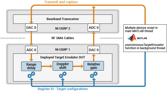
The target emulator is configured with a radar scenario and emulates the responses of up to eight moving targets continuously and in real time. The radar scenario state is updated in a parallel process from MATLAB® using Parallel Computing Toolbox™.
In the main MATLAB process, you follow these steps:
Configure the first radio as a radar target emulator and simulate a radar scenario in a parallel process using the
asynchronousTargetEmulatorhelper function.Configure the second radio as a baseband transceiver.
Transmit a radar pulse train.
Capture the response of the target emulator.
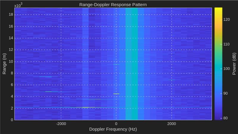
Plot the range-Doppler response.
Repeat steps 3 to 5 until the radar target emulation scenario is complete.
Prerequisites
This example uses the target emulator bitstream from the Radar Target Emulation on NI USRP Radio example. Before you run this example, follow these steps:
Run the Radar Target Emulation on NI USRP Radio example to generate a bitstream for the target emulation design, deploy the bitstream on the FPGA, and verify the design running on your radio.
Open this example in MATLAB by using the
openExamplefunction:openExample("wt/RealTimeTargetEmulatorExample")Copy these files into the new example working directory:
The hand-off information file,
wtRadarTargetEmulatorSL_wthandoffinfo.matThe bitstream (
.bit) and device tree (.dts) file, which are generated in the project folderThe generated host interface setup function file,
gs_wtRADARTargetEmulatorSL_setup.m
Start Parallel Process Pool
Use the parpool function to start a pool of two process workers.
if ~canUseParallelPool()
    error("Parallel Computing Toolbox is required to run this host interface script.")
end
if ~exist("pool","var") || ~isvalid(pool)
    delete(gcp('nocreate'));
    % Create new parallel pool
    pool = parpool("Processes",2);
end
Get Radar Scenario Parameters
Customize the simulation by editing helperRadarTargetSimulationSetup helper function. Update the sample rate (Fs) and center frequency (Fc) for your radio hardware.
Run the target simulator setup helper function to get the default simulation parameters. You update the simulation parameters for each of the targets later in the example in the asynchronousTargetEmulator helper function.
sim_in = helperRadarTargetSimulationSetup();
Select Radios
Call the radioConfigurations function. The function returns all available radio setup configurations that you saved using the Radio Setup wizard.
savedRadioConfigurations = radioConfigurations;
To update the menu with your saved radio setup configuration names, click Update. Then select the radio to use as the target emulator, radioNameTargetEmulator, and the radio to use as the pulse radar, radioNameRadar.
savedRadioConfigurationNames = [string({savedRadioConfigurations.Name})];
radioNameTargetEmulator = savedRadioConfigurationNames(1);
radioNameRadar = savedRadioConfigurationNames(1);
Evaluate the transmit and receive antennas available on the radio device you are using as the pulse radar. You use these values to configure transmit and capture antennas later in the script.
availableReceiveAntennas = hCaptureAntennas(radioNameRadar);
availableTransmitAntennas = hTransmitAntennas(radioNameRadar);
Configure Radios
Configure radioNameRadar as a baseband transceiver to use as a pulse radar.
Specify the baseband transceiver parameters for your radio and tune the gain and center frequency according to your setup. Additionally, tune the gains and center frequencies of the target emulator radio in the asynchronousTargetEmulator function. Since the required gain values will vary across different radios and by the amount of attenuation added, you might need to run the example multiple times with steadily increasing gains.
When you specify antennas for the baseband transceiver, ensure that they are connected via SMA cable and attenuator to the corresponding antenna of the target emulator radio. The baseband transceiver transmit antenna must be connected to the target emulator DUT input antenna. Likewise, the target emulator DUT output antenna must be connected to the baseband transceiver capture antenna.
centerFrequency = sim_in.Fc;
sampleRate = sim_in.Fs;
rxGain = 45;
txGain = 40;
if ~exist("bbtrx","var")
    radio = radioConfigurations(radioNameRadar);
    bbtrx = basebandTransceiver(radio,Preload=true, ...
        CaptureAntennas=availableReceiveAntennas(1), ...
        TransmitAntennas=availableTransmitAntennas(1), ...
        CaptureDataType="int16", ...
        TransmitDataType="int16", ...
        CaptureCenterFrequency=centerFrequency, ...
        TransmitCenterFrequency=centerFrequency, ...
        CaptureRadioGain=rxGain, ...
        TransmitRadioGain=txGain, ...
        SampleRate=sampleRate);
Specify Preload as true to load the FPGA image onto the radio ahead of calling transmit or capture, which reduces the initialization time of the first function call and prevents the radio time from being reset. There is still a short initialization delay the first time you call the capture function. Capture ten samples now to avoid this delay later.
    [~] = capture(bbtrx,10);
end
Configure Transmit Waveform
Format the transmit waveform pulse train according to the slow time dimension length. Then scale and convert to a 16-bit integer.
txPulseTrain = repmat( ...
    [sim_in.txSignal; zeros(sim_in.pulsePeriodSamples-length(sim_in.txSignal),1)], ... % Full period of tx signal
    sim_in.VelDimLen, 1); % Repeated by the velocity (slow time) dimension length
txPulseTrain = int16(txPulseTrain*double(intmax('int16'))); % Scale and convert to int16
captureLength = length(txPulseTrain);
Specify a scheduling offset. This offset is the number of seconds in the future the transmit and receive operations starts. The offset must be long enough to account for the loading of the transmit waveform into the onboard radio memory buffer before the start of the transmission.
scheduleTimeOffset =  1;
1;Configure Detection
Create a phased.RangeDopplerResponse (Phased Array System Toolbox) object to analyze the received responses.
rdResponse = phased.RangeDopplerResponse(...
    DopplerFFTLengthSource='Property', ...
    DopplerFFTLength=sim_in.VelDimLen, ...
    PRFSource='Property',PRF=sim_in.PRF,...
    SampleRate=sim_in.Fs, ...
    DopplerOutput='Frequency');
Create a phased.RangeDopplerScope (Phased Array System Toolbox) object to visualize each response. When re-running the example, to improve consistency between frames, consider setting fixed color axis limits according to the power levels in your setup.
scope = phased.RangeDopplerScope(IQDataInput=false,ResponseUnits="db",ColorLimits= "Auto");
Start Target Emulation in Background Process
Open the asynchronousTargetEmulator live function. This live function initializes your radio as a target emulator and simulates a radar scenario by regularly updating the simulation state. Edit the live function script with your generated bitstream and hand-off information file. Optionally, customize the radar scenario for the simulation.
open asynchronousTargetEmulator.mRun the radar target emulation scenario in a background process. The simulated scenario is initially configured and then asynchronously updated in the asynchronousTargetEmulator function.
Use parfeval to run the asynchronousTargetEmulator function in a parallel process. If the bitstream is not already loaded, check the box to also load the bitstream.
programBitstream = false;
scenarioFuture = parfeval(pool,@asynchronousTargetEmulator,0,radioNameTargetEmulator,programBitstream);
false;
scenarioFuture = parfeval(pool,@asynchronousTargetEmulator,0,radioNameTargetEmulator,programBitstream);In the main MATLAB process, use the baseband transceiver to transmit the pulse train and capture and plot the response. Repeat this process until the scenario simulation running on the target emulator finishes.
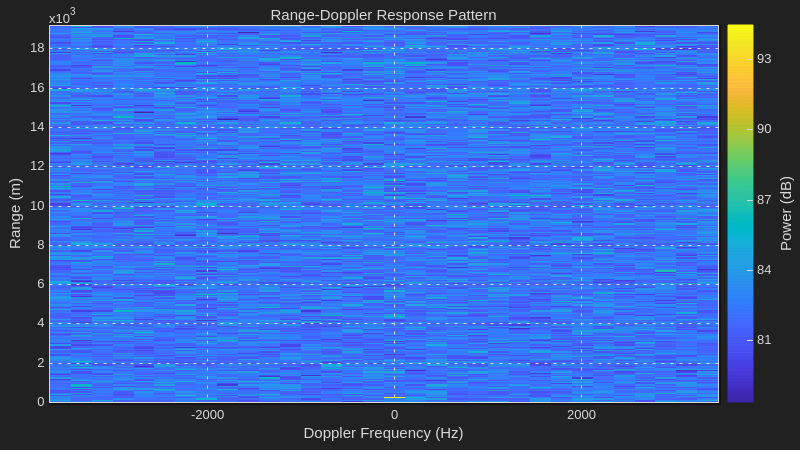
Because the process runs asynchronously, the initial frames appear before the scenario simulation starts, and the final frame appears after it ends. The scope image illustrates this behavior.
out.ValidOut = true(1,captureLength);
while ~strcmp(scenarioFuture.State,'finished')
    scheduledTime = getRadioTime(radio) + scheduleTimeOffset;
    transmit(bbtrx,txPulseTrain,"once",StartTime=scheduledTime);
    out.DataOut = capture(bbtrx,captureLength,StartTime=scheduledTime);
    helperVisualizeRadarTargetSimulationScope(out,sim_in,rdResponse,scope);
end
if ~isempty(scenarioFuture.Error)
    error("Error occured in parallel process. Message: "+scenarioFuture.Error.message);
    % Likely requires fixing in asynchronousTargetEmulator.m
end
The image shows an example of the scope running the radar scenario.