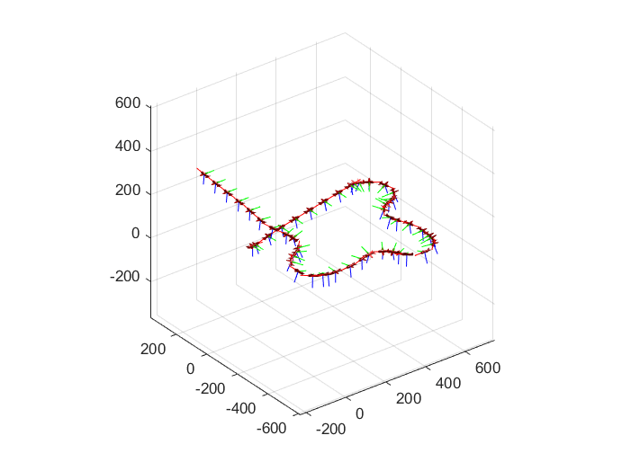
Evolve UAV Plant Model from Low to High Fidelity
R2026bThis example shows you how to evolve your UAV plant model continuously to stay in sync with the latest information available.
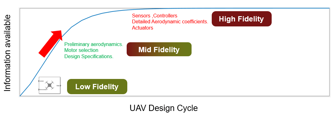
High-fidelity UAV plant models require data from flight and wind tunnel tests that are unavailable early in design. Start with a low-fidelity Guidance block and progressively add control and dynamics layers through medium- and high-fidelity stages. The medium-fidelity model lets you tune and test guidance algorithms with limited plant data before validating with a high-fidelity model later.
Open Project Files
Open the Simulink® project provided in this example.
openProject('FidelityExample');
This project contains these Simulink models:
FidelityStepResponse— Simulates the response of a UAV model in roll, height, and airspeed step inputs. The model contains low-fidelity, medium-fidelity, and high-fidelity variants.FidelityPathFollowing— Simulates a UAV in a path-following mission. The model contains low-fidelity, medium-fidelity, and high-fidelity variants.Outer_Loop_Autopilot— Height-pitch and airspeed-throttle outer-loop controller for the medium-fidelity model.HighPlantModel— High-fidelity UAV plant model.
Simulate Low-Fidelity Step Response
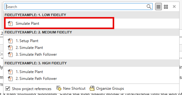
To set up and run the FidelityStepResponse model with the low-fidelity variant, click the Simulate Plant shortcut in the Low Fidelity group of the project shortcuts.
The model stores the output in the workspace, which is plotted in the next section of this example.
Examine the Guidance Model block in the FidelityStepResponse/FixedWingModel/LowFidelity subsystem.
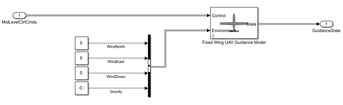
This block is a reduced-order model for a UAV that integrates the controller with the dynamics of the aircraft. In the Configuration tab of the UAV Guidance block, inspect the gains set for height, airspeed, and roll response. These gains enable the low-fidelity model to achieve the response times in the design specification summarized in this table.
Design Specification | Response Time (within 2%) | Step Change |
|---|---|---|
Roll | 2.5 seconds | 30 degrees |
Height | 4.5 seconds | 5 m |
Airspeed | 0.6 seconds | 1 m/s |
Set Up Medium-Fidelity Model
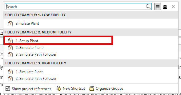
To set up the FidelityStepResponse model with the medium-fidelity variant, click the Setup Plant shortcut under the Medium Fidelity group of the project shortcuts. The medium-fidelity variant of the model incorporates preliminary aerodynamic coefficients and thrust curves to increase the model accuracy.
Examine the Vehicle Dynamics tab in the model under FidelityStepResponse/FixedWingModel/Mid Fidelty/UAV Plant Dynamics/Vehicle Dynamics.
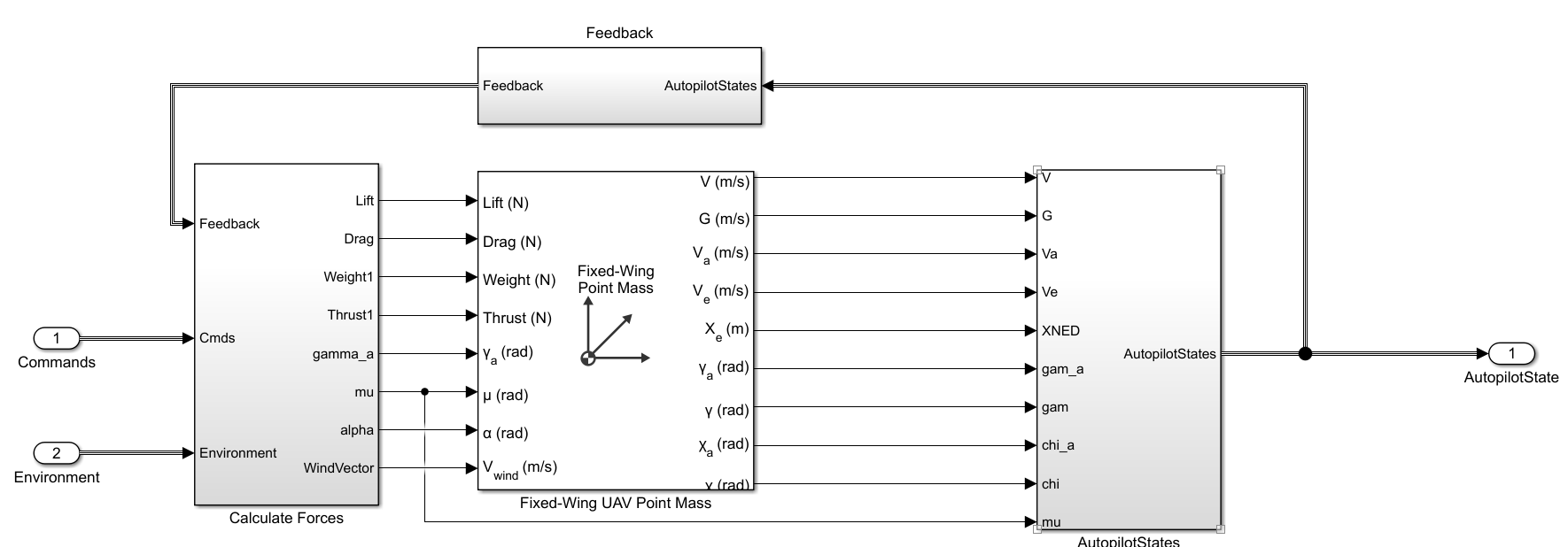
The medium-fidelity model represents the UAV as a Fixed-Wing UAV Point Mass with the primary control variables being the angle of attack and roll. This medium-fidelity plant model takes in roll, pitch, and thrust as control inputs. The point mass block assumes instantaneous dynamics of roll and angle of attack. This model uses a transfer function to model roll lag based on the roll-response specification from the previous step.
The medium-fidelity aircraft controls pitch instead of angle of attack. Since the angle of attack is an input to the point mass block, the plant model converts pitch to alpha using the following equation.
+
, and represent pitch, flight path angle in the wind frame, and angle of attack respectively.
Unlike the low-fidelity model, the medium-fidelity model splits the autopilot from the plant dynamics. The medium-fidelity plant requires an outer-loop controller for height-pitch and airspeed-throttle control. The predefined controllers use standard PID-tuning loops to achieve satisfactory response without overshoot. To inspect the outer-loop controller, open the Outer_Loop_Autopilot Simulink model.
Simulate Medium-Fidelity Step Response
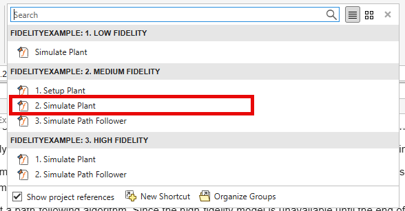
After you set up the FidelityStepResponse model with the medium-fidelity variant, simulate the step response by clicking the Simulate Plant shortcut under the Medium Fidelity group of the project shortcuts.
After the simulation finishes, the example plots the step responses for the medium- and low-fidelity models.
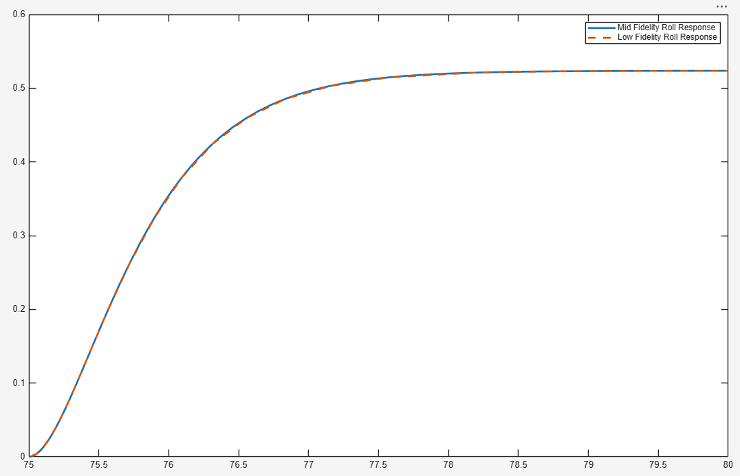
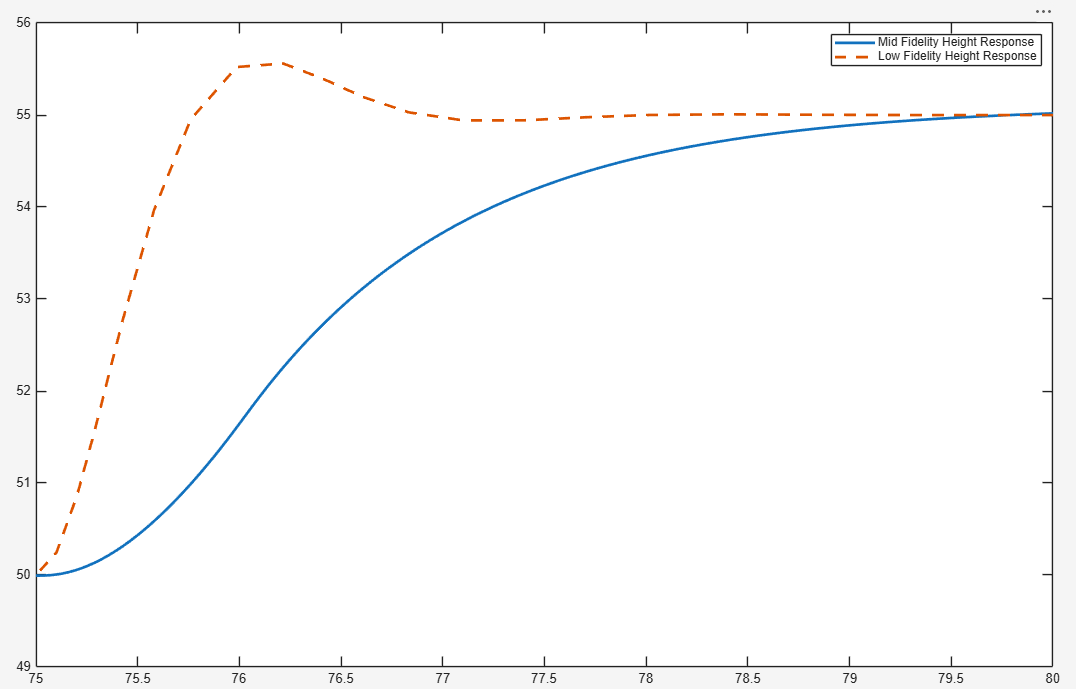
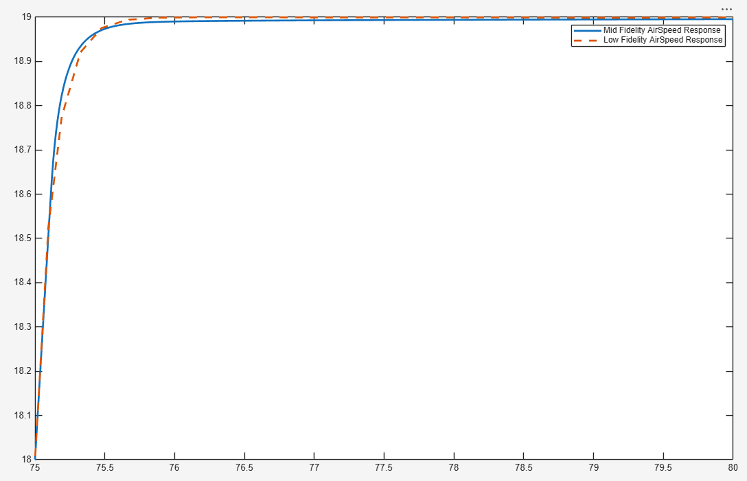
The model meets the design criteria shown in the table below, achieving an airspeed settling time of 0.6 seconds and a height response of 4.1 seconds. However, the height response is slower than the low-fidelity variant. The additional aerodynamic constraints on the medium-fidelity plant account for this lag.
Design Specification | Response Time (within 2%) | Step Change |
|---|---|---|
Roll | 2.5 seconds | 30 degrees |
Height | 4.5 seconds (Achieved) | 5 m |
Airspeed | 0.6 seconds (Achieved) | 1 m/s |
Simulate Path-Following Algorithm
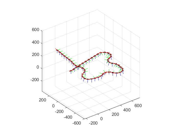
With a more accurate response from the UAV medium-fidelity model, you can now test Waypoint Follower or guidance algorithms to follow waypoints. To simulate the medium-fidelity UAV model in a path-following mission, click the Simulate Path Follower shortcut under the Medium Fidelity group of the project shortcuts.
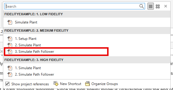
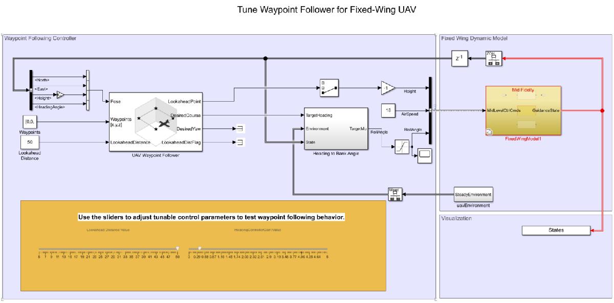
The medium-fidelity UAV follows the desired path accurately.
Simulate High-Fidelity Step Response
The previous steps used the medium-fidelity model to test a path follower design with simple aircraft parameters available early in the design process. However, continuing to add fidelity captures UAV control response for more complex situations. For example, more detailed aerodynamic coefficients let you analyze complex motions such as doublet maneuvers. Adding actuator dynamics lets you study effects on inner-loop attitude controllers, which can cause destabilization. In this step, you examine a high-fidelity plant with these added dynamics to study the change in response.
The high-fidelity plant inputs all forces and moments to a 6DOF (Quaternion) (Aerospace Blockset) block, adds on-board sensors, and models actuator dynamics for the UAV. Unlike the medium-fidelity plant, the high-fidelity version does not take attitude inputs directly. Instead, an inner-loop controller controls attitude. Additionally, a yaw compensation loop balances the non-zero sideslip. The model reuses the outer-loop controller designed for the medium-fidelity model. To validate that the medium-fidelity model provides useful intermediate information, use the response of the high-fidelity model.
To simulate and visualize the high-fidelity step response, click the Simulate Plant shortcut under the High-Fidelity group of the project shortcuts.
After the simulation finishes, the example plots the step responses for the high- and medium-fidelity models.
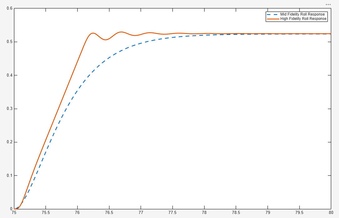
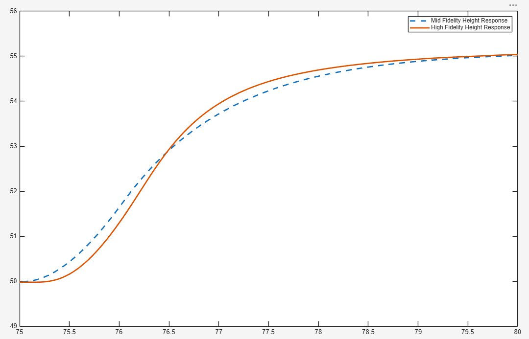
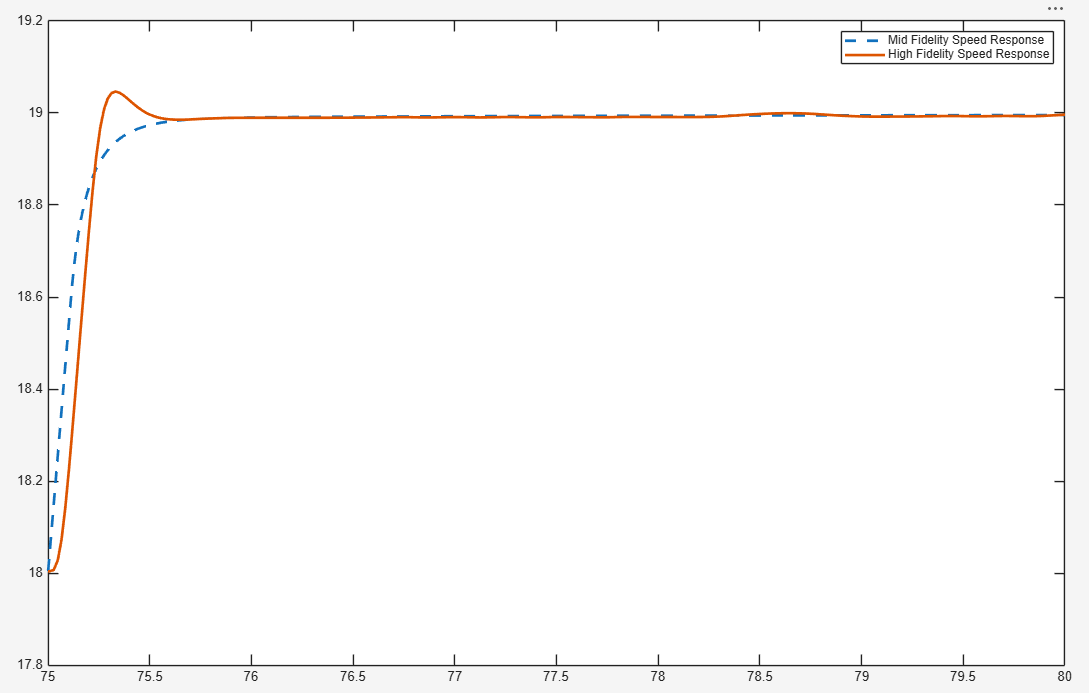
Despite the added complexity, the trajectory matches well with the medium-fidelity model. The design specifications remain consistent at the high-fidelity stage. This similarity shows that the medium-fidelity plant models UAV dynamics accurately.
Design Specification | Response Time (within 2%) | Step Change |
|---|---|---|
Roll | 2.5 seconds | 30 degrees |
Height | 3.9 seconds | 5 m |
Airspeed | 0.6 seconds | 1 m/s |
Simulate High-Fidelity Path-Following Algorithm
Toward the end of the design cycle, the high-fidelity model finally becomes available. To get the final UAV path-following characteristics, you can now test the guidance algorithm developed in previous steps on the high-fidelity plant. Click the Simulate Path Follower shortcut under the High-Fidelity group of the project shortcuts.
The model obtains a similar response to the medium-fidelity model using the guidance and outer-loop control parameters. This validates the guidance algorithm with a high-fidelity plant.