Model Alternative VTOL UAV Configuration
This example shows you how to configure the VTOL UAV template to simulate an alternative VTOL UAV configuration.
The VTOL UAV template models the UAV in a tilt-rotor configuration with four rotors in the puller configuration. In the takeoff, landing, and hover modes, all four rotors point vertically upward. When transitioning to cruise mode, the front two rotors tilt forward to a horizontal position to provide thrust for the UAV, while the rear two rotors remain in the vertical orientation and provide no thrust.
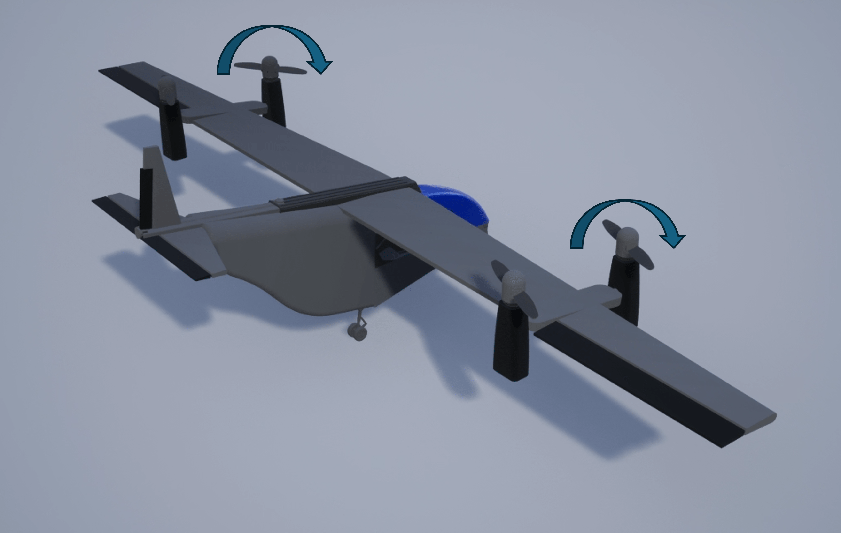
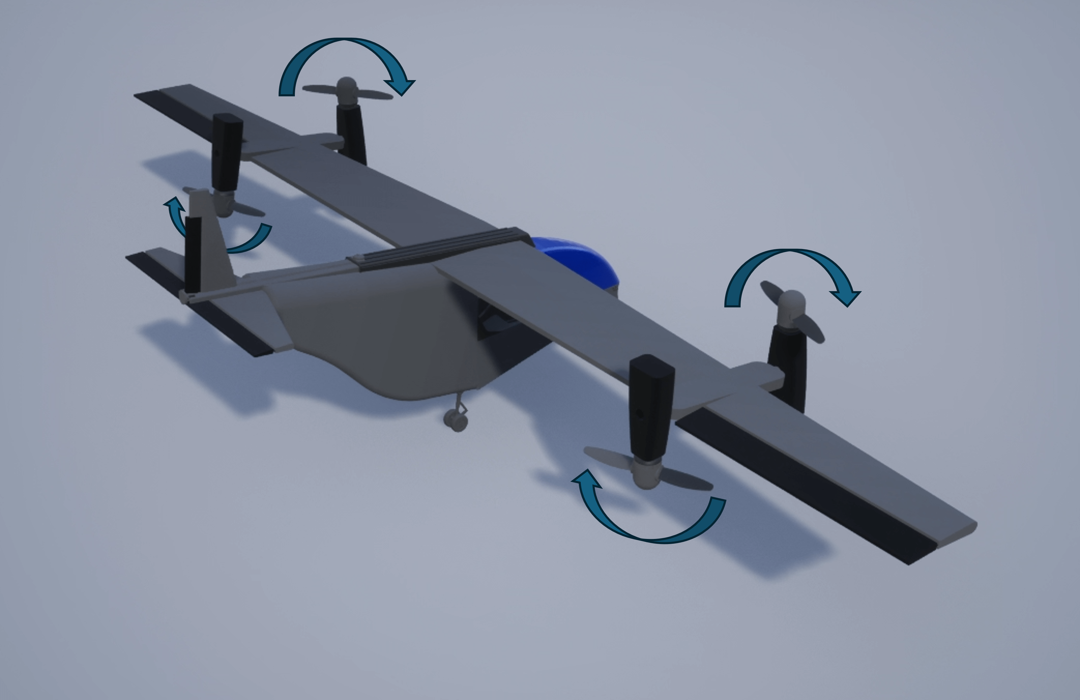
However, in the alternative VTOL UAV configuration, two front rotors of the UAV are pushers, and the two rear rotors are pullers. In the takeoff, landing, and hover modes, the front two rotors point vertically upward, and the rear two rotors point vertically downward. When transitioning to cruise mode, the front two rotors tilt forward to a horizontal position to provide thrust for the UAV, while the rear two rotors tilt backward to a horizontal position and provide additional thrust.
Getting Started
Open the example live script and the directory that contains the VTOLRefApp.prj project file project by running openExample('uav/ModelAlternativeVTOLUAVConfigurationExample') in the command window.
After opening the example live script and the directory, you must open the VTOLRefApp.prj project file to access the Simulink® model, supporting files, and project shortcuts that this example uses.
% Open the Simulink project
prj = openProject("VTOLApp/VTOLRefApp.prj");
Open the alternative VTOL UAV model.
open_system("Alternative_VTOLTiltrotor")Compared to the VTOL UAV template model, the alternative VTOL UAV model contains modifications to the Propulsion subsystem, output bus interface, and multicopter scheduler subsystem.
Propulsion Subsystem Modifications
Open the Propulsion subsystem of the alternative VTOL UAV configuration.
blockpath = Simulink.BlockPath(["Alternative_VTOLTiltrotor/Digital Twin/UAV Dynamics","Alternative_VTOLDynamics/Force and Moments/Propulsion"]);
open(blockpath)
The Propulsion subsystem of the alternative VTOL UAV contains modifications to the tilt servo dynamics, rotor assembly, and rotor parameters, which enables the UAV to tilt all four motor-rotor pairs and to set the rear two motors to the pusher configuration.
Tilt Servo Dynamics Subsystem Modifications
Compared to the default VTOL UAV model, the Tilt Servo Dynamics subsystem of the alternative VTOL UAV model contains these additional blocks to simulate the servo dynamics of tilting the rear two motor:
Inport blocks for motor tilt angle inputs (
TiltCandTiltD)Gain blocks with values of
pi/2Transfer function blocks (
Servo Dynamics2andServo Dynamics3)Initial conditions, set to match the front two rotor tilt angles
Motor tilt angle outputs (
Tilt3andTilt4)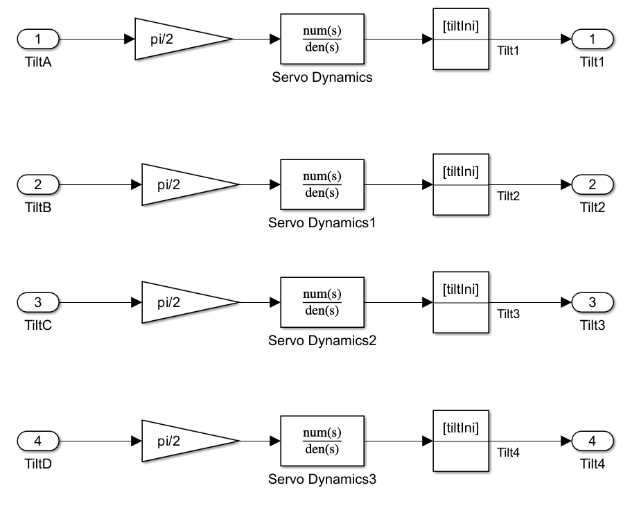
The multicopter scheduler subsystem generates the Actuator.Tilt3 and Actuator.Tilt4 signals, connected to the TiltC and TiltD input ports respectively. The motor tilt angle outputs are connect to the RotorC and RotorD variables.

Rotor Assembly Subsystem Modifications
In the default VTOL UAV model, the Tilt inputs of the Rotor Assembly 3 and Rotor Assembly 4 subsystems are set to a constant angle of 0 degrees, which corresponds to the rear two rotors constantly facing vertically upward.
In the alternative VTOL UAV model, the Tilt inputs of the Rotor Assembly 3 and Rotor Assembly 4 subsystems connect to the RotorC and RotorD variables. This enables the rear two rotors to tilt in accordance with the output of the Tilt Servo Dynamics subsystem.
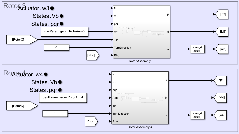
Additionally, the output ports of the Rotor blocks in the Rotor Assembly 3 and Rotor Assembly 4 subsystems now connect to Gain blocks with values of -1. These gains reverse the signs of the total force outputs of the Rotor blocks, which configure rear two propellers as pushers.

Rotor Parameters Modifications
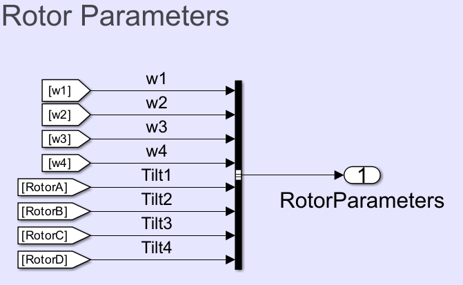
The Bus Creator block in the Rotor Parameters section groups the control signal into the RotorCtrlBus bus. In the alternative VTOL UAV model, the Bus Creator block has the two additional input signals, Tilt3 and Tilt4.
Output Bus Interface Modifications
In the default VTOL UAV model, the RotorCtrlBus consists of these elements:
w1— Rotor 1 PWMw2— Rotor 2 PWMw3— Rotor 3 PWMw4— Rotor 4 PWMTilt1— Rotor 1 tilt PWMTilt2— Rotor 2 tilt PWM
In the alternative VTOL UAV model, the Tilt3 and Tilt4 elements of RotorCtrlBus control the rotor 3 tilt PWM and rotor 4 tilt PWM, respectively.
Use Model Explorer to examine the contents of the modified rotor control bus.

Multicopter Scheduler Subsystem Modifications
Open the multicopter scheduler subsystem of the alternative VTOL UAV configuration.
blockpath = Simulink.BlockPath(["Alternative_VTOLTiltrotor/Autopilot/Controller", "Alternative_VTOLAutopilotController/Low level controller/Scheduler/Subsystem"]);
open(blockpath);
The multicopter scheduler subsystem of the alternative VTOL UAV has been modified to provide additional control for the rear two motors during the hover, transition, back transition, and cruise phases.
Hover, Transition, and Back Transition Cases Modifications
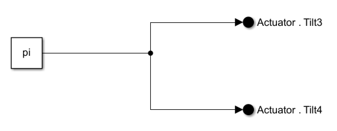
In the hover, transition, and back transition phases, the rear two rotors of the alternative VTOL UAV point vertically downward. To simulate this, the Hover, Transition, and Back Transition cases of the scheduler have been modified by adding a constant input of pi to the Actuator.Tilt3 and Actuator.Tilt4 signals.
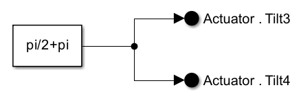
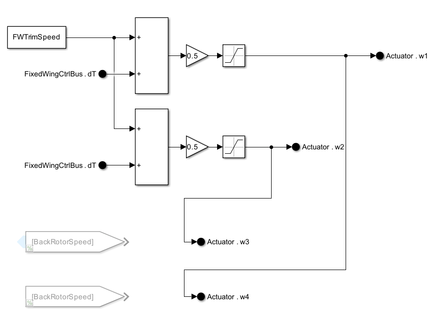
Fixed Wing Case Modifications
In the fixed-wing phase, the rear two rotors of the alternative VTOL UAV point horizontally backward. To simulate this, the FixedWing case of the scheduler has been modified by adding a constant input of pi/2+pi to the Actuator.Tilt3 and Actuator.Tilt4 signals.
The alternative VTOL UAV does not simulate a wind down mechanism during back transition. To disable the wind down mechanisms, the blocks in Tilt WindDown Mechanisms section have been commented out.
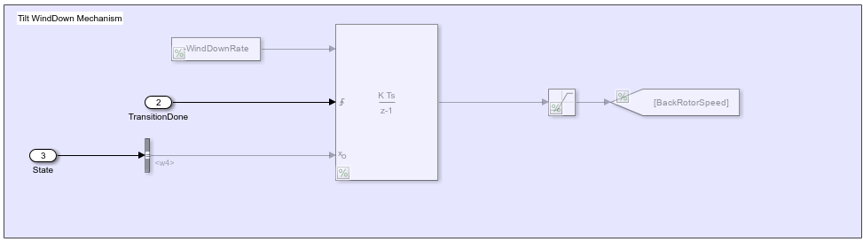
In contrast to the default VTOL UAV, which uses only the front two motors for thrust, the alternative VTOL UAV uses all four motors to provide thrust during fixed-wing mode. To simulate this in the alternative VTOL UAV model, BackRotorSpeed has been disabled, and the inputs to Actuator.w3 and Actuator.w4 have been replaced with signals used for Actuator.w2 and Actuator.w2, respectively. This enables the front and rear motors on each side to have matching RPMs.
In addition, the model adds a Gain block with a value of 0.5 is added to the throttle signal outputs. This matches the total thrust of the alternative VTOL UAV to that of the default VTOL UAV, which enables the two configurations to use the same set of fixed-wing control gains.
Simulate Full Transition Mission
To simulate the full transition mission for the alternative UAV configuration, select the Set Up Full Transition Mission shortcut in the Alternative UAV configuration Mission section, and run the Alternative_VTOLTiltrotor.slx model.
Before resuming to other examples in this example series, you must close the VTOLRefApp.prj Simulink project by running this command in the Command Window:
close(prj)