Design Quadrotor Position and Attitude Controllers for ArduCopter
This example shows how to use the UAV Toolbox Support Package for ArduPilot® Autopilots to design position and attitude controller for ArduCopter in Simulink®. This example is designed to run with the ArduPilot Host Target, allowing you to perform Software-in-the-Loop (SITL) simulation.
Prerequisites
If you are new to Simulink, watch the Simulink Quick Start video.
Model
Open the PositionAltitudeAttitudeController model.
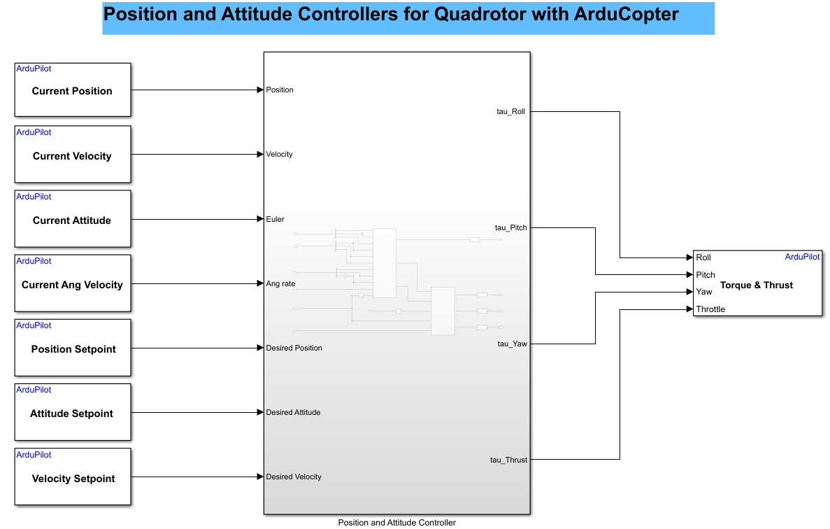
This model consists of two subsystems:
Position & Attitude Controller
Attitude Controller
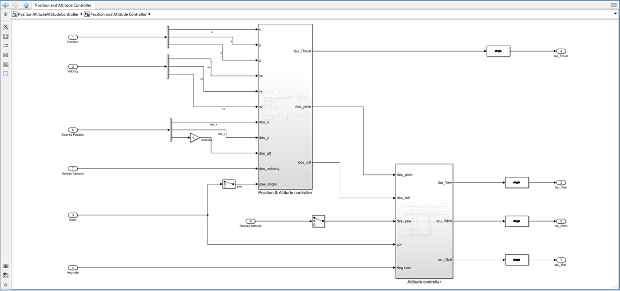
Position & Attitude Controller
This controller is responsible for managing the overall position and orientation (attitude) of the ArduCopter.
It takes in the current state (position and velocity) and the desired state (desired position and velocity), and computes the required thrust and desired attitude (pitch and roll commands).
Attitude Controller
This controller takes the desired attitude (from the Position & Attitude Controller) and the current attitude (from estimators) to compute the required torques around each axis to achieve the desired orientation.
Run the Model
This section guides you through configuring and the controller model in Simulink, using the UAV Toolbox Support Package for ArduPilot Autopilots. You will configure the Simulink model, and use Mission Planner to monitor and verify the simulation.
Configure the Simulink Model
1. Open the PositionAltitudeAttitudeController example model. The hardware board is already set to Host Target.
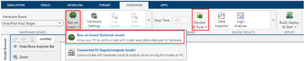
2. Run Monitor and Tune simulation for the model.
Go to Hardware tab, and click Monitor & Tune to configure the model for simulation.
3. Open Mission Planner.
It should automatically connect via UDP port 14550 once MAVProxy starts.
If it does not connect automatically, manually connect using port 14550.
4.In Mission Planner, you can now control the drone. Create a mission and start it to initiate the flight.
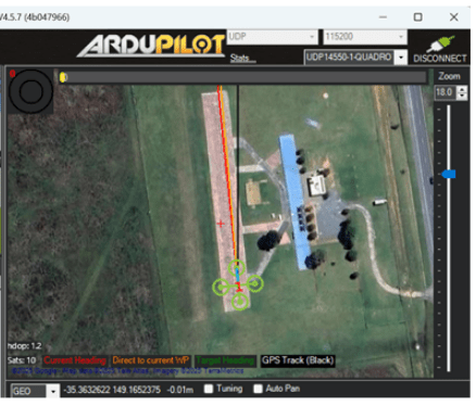
Fly the copter. For more information, see Mission Planner Flight PLAN
Once the mission is in progress, you should observe the vehicle following the planned mission.
5. After the mission is complete, disarm the drone to ensure it is safely powered down.
Other Things to Try
Try executing this example on an actual hardware.
Try with your own custom airframe by replacing the mixer matrix.
Experiment with different control strategies in the controller block.