FRS/GMRS Receiver in Simulink
This example shows how to implement a walkie-talkie receiver using Simulink® and Communications Toolbox™. The specific radio standard that this example follows is FRS/GMRS (Family Radio Service / General Mobile Radio Service) with CTCSS (Continuous Tone-Coded Squelch System). You can use simulated signals, captured signals, or received signals from a commercial walkie-talkie using the Communications Toolbox Support Package for RTL-SDR Radio.
This example is designed to work with USA standards for FRS/GMRS operation. The technical specifications for these standards can be found in the reference list below. Operation in other countries may or may not work.
Required Hardware and Software
To run this example using captured signals, you need the following software:
To receive signals in real time, you also need the following hardware:
RTL-SDR radio
Walkie-talkie
and the following software
For a full list of Communications Toolbox supported SDR platforms, refer to the "MATLAB and Simulink Hardware Support for SDR" section of Software-Defined Radio (SDR).
Introduction
For an introduction on FRS/GMRS technology and demodulation of these signals, refer to the FRS/GMRS Walkie-Talkie Receiver example.
Running the Example
To run the example using simulated signals, select the FRS/GMRS Signal Generator block as the source using the Signal Source Selector block. Double click the FRS/GMRS Signal Generator block to select the CTCSS code and source type as one of 'Single tone', 'Chirp', or 'Audio'. Then click the run button.
To run the example using captured signals, select the FRS/GMRS Captured Signal block as the source using the Signal Source Selector block. Then click the run button.
To run the example using the RTL-SDR radio as the source, select the RTL-SDR Receiver block as the source using the Signal Source Selector block. Then click the run button. Turn on your walkie-talkie, set the channel to be one of the 14 channels (numbered 1 to 14) and the private code to be either one of the 38 private codes (numbered 1 to 38) or 0, in which case no squelch system is used and all received messages are accepted. Note that the private codes above 38 are digital codes and are not implemented in this example.
Double-click the Channel Number block and select the same channel number as the walkie-talkie. Double-click the CTCSS Code block and set the CTCSS Code to the private code you set in the walkie-talkie. Run the model, and see if you can hear your voice come out of the computer speakers. If not, try adjusting the Detection Threshold block value downward slightly. You can change the channel and private code without stopping and restarting the model.
If you hear some dropouts or delay in the sound, run the model in Accelerator mode. From the model menu, select Simulation->Accelerator, then click the run button. If you still experience dropouts or delay in Accelerator mode, try running the model in Rapid Accelerator mode.
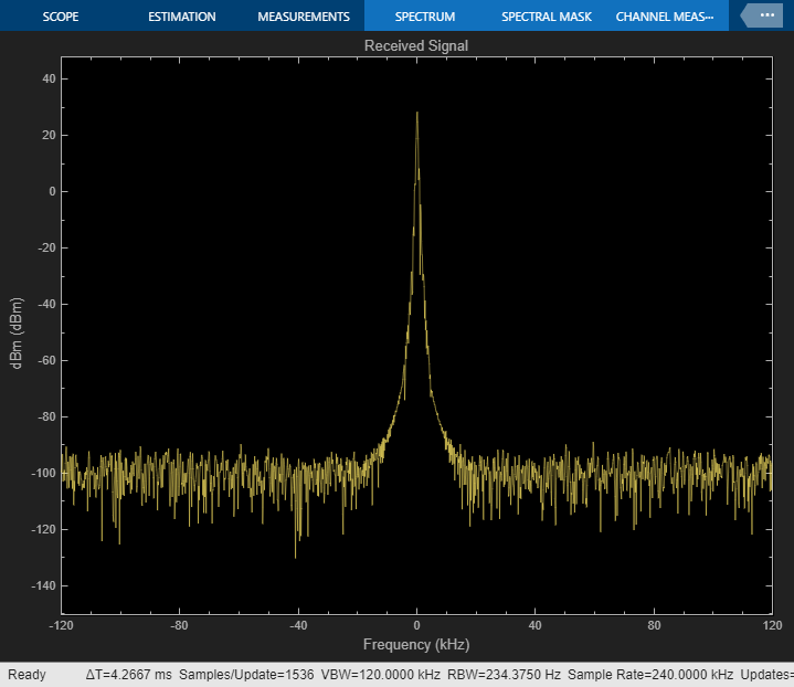
The "Signal Spectrum" shows the spectrum of the received signal at the input of the Channel Selector block. You can observe how the spectrum changes as you speak into your walkie-talkie.
Receiver Structure
The following block diagram summarizes the receiver structure. The processing has four main parts: Signal Source, Channel Selector, FM Demodulator, and CTCSS processing.

Signal Source
This example can use three signal sources:
''Simulated Signal'': Simulated FRS/GMRS signal at 240e3 samples/sec
''Captured Signal'': Over-the-air signals written to a file and sourced using a baseband file reader block at 240e3 samples/sec
''RTL-SDR Radio'': RTL-SDR radio at 240e3 samples/sec. Use a walkie-talkie as a transmitter. Set the channel number to the channel number of your walkie-talkie.
Channel Selector
The receiver removes the DC component and applies a variable gain to the received signal to obtain an approximately known amplitude signal with reduced interference. The receiver then applies a low pass channel separation filter to reduce the signals from adjacent channels. The gap between adjacent channels is 25 kHz, which means the baseband bandwidth is, at most, 12.5 kHz. Thus, we choose the cutoff frequency to be 10 kHz.
Next, a channel selector computes the average power of the filtered signal. If it is greater than a threshold (set to a default of 10%), the channel selector determines that the received signal is from the correct channel and allows the signal to pass through. In the case of an out-of-band signal, although the channel separation filter reduces its magnitude, it is still FM modulated and the modulating signal will be present after FM demodulation. To completely reject such a signal, the channel selector outputs all zeros.
FM Demodulator
This example uses the FM Demodulator Baseband block whose sample rate and maximum frequency deviation are set to 240 kHz and 2.5 kHz, respectively.
CTCSS
First, a decimation filter converts the sampling rate from 240 kHz to 8 kHz. This rate is one of the native sampling rates of your host computer's output audio device. Then, the CTCSS decoder computes the power at each CTCSS tone frequency using the Goertzel algorithm and outputs the code with the largest power. The Goertzel algorithm provides an efficient method to compute the frequency components at predetermined frequencies, that is, the tone code frequencies used by FRS/GMRS.
The model compares the estimated received code with the preselected code and then sends the signal to the audio device if the two codes match. When the preselected code is zero, it indicates no squelch system is used and the decision block passes the signal at the channel to the audio device no matter which code is used.
Finally, a high pass filter with a cutoff frequency of 260 Hz filters out the CTCSS tones, which have a maximum frequency of 250 Hz. Use an Audio Device Writer block to play the received signals through your computer's speakers. If you do not hear any sound, please select another device using the DeviceName parameter of the Audio Device Writer block.
Audio Output
Before the audio device, a high pass filter with a cutoff frequency of 260 Hz is used to filter out the CTCSS tones (which have a maximum frequency of 250 Hz) so that they are not heard.
The Audio Device Writer block is set up by default to output to the current audio device in your system preferences.
Exploring the Example
The CTCSS decoding computes the DTFT (Discrete-Time Fourier Transform) of the incoming signal using the Goertzel algorithm and computes the power at the tone frequencies. Because the tone frequencies are very close to each other (only 3-4 Hz apart) the block length of the DTFT should be large enough to provide enough resolution for the frequency analysis. However, long block lengths cause decoding delay. For example, a block length of 16384 will cause 2 seconds of delay, since the CTCSS decoder operates at an 8 kHz sampling rate. This creates a tradeoff between detection performance and processing latency. The optimal block length may depend on the quality of the transmitter and receiver, the distance between the transmitter and receiver, and other factors. You are encouraged to change the block length in the initialization function by navigating to the helperFRSReceiverConfig function and changing the value of the CTCSSDecodeBlockLength field. This will enable you to observe the tradeoff and find the optimal value for your transmitter/receiver pair.
When the FRS/GMRS Signal Generator is selected as the source, you can change the CTCSS tone amplitude parameter of this block and observe how this affects the signal spectrum.
Appendix
The following script is used in this example:
References
You can also select a web site from the following list:
Americas
- América Latina (Español)
- Canada (English)
- United States (English)
Europe
- Belgium (English)
- Denmark (English)
- Deutschland (Deutsch)
- España (Español)
- Finland (English)
- France (Français)
- Ireland (English)
- Italia (Italiano)
- Luxembourg (English)
- Netherlands (English)
- Norway (English)
- Österreich (Deutsch)
- Portugal (English)
- Sweden (English)
- Switzerland
- United Kingdom (English)