Getting Started with Image Processing Algorithms for Parrot Minidrones
This example shows you how to create a Simulink® model that uses the images from a Parrot® minidrone's downward-facing camera to develop a simple image-processing algorithm to be deployed on Parrot minidrone.
Introduction
The Parrot minidrones are equipped with a downward-facing camera that provides images measuring 120-by-160 pixels. The image is internally used by the drone to calculate the optical flow of the drone. The image data is also available to the user to develop vision-based algorithms.
The Simulink Support Package for Parrot Minidrones provides a Simulink template that contains an inport that obtains the images captured by the drone's camera. You can use this template to develop image-processing algorithms. The output of the image-processing algorithm can be used as an additional input to control the flight of the drone.
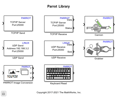
The image data obtained from the downward-facing camera is a 4-by-9600 array of type uint8, in Y1UY2V format. This is an encoded format of the standard YUV color space. The template also contains the Parrot Image Conversion block, which converts the image from Y1UY2V format to YUV or RGB format.
The block can also be found in the Simulink library. To access the Parrot Image Conversion block from the Simulink Library Browser:
1. Enter slLibraryBrowser at the MATLAB prompt.
2. In the Simulink Library Browser, navigate to Simulink Support Package for Parrot Minidrones.
In this example, you will learn how to use the Code Generation Template For Image Processing and Control to:
Obtain an image from the downward-facing camera and convert it using the Parrot Image Conversion block
Perform analysis of converted image to detect any red object in the image
Run one of the motors of the drone if a red object is detected
Prerequisites
If you are new to Simulink, complete the Interactive Simulink Tutorial.
To setup and run a Simulink model on a Parrot minidrone, follow the example described in Getting Started with Simulink Support Package for Parrot Minidrones.
Download and install the Computer Vision Toolbox. This requires a separate license.
Required Hardware
To run this example, you will need the following hardware:
Parrot Rolling Spider or Parrot Mambo with a fully charged battery and propellers connected to the motors.
Bluetooth Low Energy (BLE) 4.0 support on the host computer
Task 1 - Develop the Image Processing Algorithm to Detect a Red Colored Object
This task shows how to develop an image processing algorithm to detect a red colored object using the image from the downward-facing camera of Parrot minidrone. This task uses blocks from Computer Vision Toolbox.
1. On the Simulink Start page, navigate to Simulink Support Package for Parrot Minidrones and select Code Generation Template For Image Processing and Control.
2. Double-click and open the Image Processing System subsystem. You can find the Image Data inport which obtains the image from the camera. This inport is connected as input to the Parrot Image Conversion block. The outputs from the block are Y, U, and V, by default.
3. Open the Parrot Image Conversion block mask and change Output color space from YUV to RGB, and select all the three channels for output (R, G, and B).
4. Add logic to binarize the image using a threshold. This logic should check the pixels in the image and find the pixels that have red as the dominant color.
To do this, check if the red component is greater than half-the-value of green and blue by at least 100, that is, Output = R - (G/2) - (B/2), which should be more than 100. If it is, then output a value of 1, for the particular pixel input. Otherwise, output zero.
You also need to add all the output 1's and compare it with a constant to ensure that more pixels are considered.
This logic could be implemented in Simulink like this:
a) Add a Product block to divide the green and blue outputs from the Parrot Image Conversion block, by half (divide by 2).
b) Use a Sum block at the output of the Product block to calculate the dominance of red color component among the three components, and then compare the output value with a threshold value of 100 (using a GreaterThan block).
c) Use another Sum block and a Compare to Constant block (with 50 as the Constant value) to consider more number of pixels (binarized images).
5. Use the output from the Compare to Constant block as the input to a Switch block. The Switch block can be used to pass a Motor Run value of 200 when the output of Compare to Constant block is more than 50, or a Motor stop value of 0 if it is less.
6. Connect the Switch block to the Vision-based Data outport.
Task 2 - Use the Vision-based Data to Control the Speed of a Motor
In this task, use the output from the Image Processing System in the Flight Control System subsystem as input data. Use the data to control a motor on the drone.
1. The Flight Control System subsystem contains a Motors outport, which expects four input values that correspond to the speed of the four motors. A mux block (Vector Concatenate block) is already connected to this output port in the template. Connect the Vision-based Data inport as the second input of the mux block, and connect a Constant block with value 200 as the first input. Connect two Constant blocks with value 0 to the other two inputs of the mux block.
2. On the toolbar of the Simulink model window, click the Deploy to Hardware icon.
If you have selected the Launch Parrot Flight Control Interface automatically after build option in the Configuration Parameters dialog box (Hardware Implementation pane > Target Hardware Resources > Build Options), the Parrot Flight Control Interface opens automatically after the build goes through successfully.
3. On the Parrot Flight Control Interface, click Start. The deployed model is now ready to analyze images obtained from the downward-facing camera of the drone, and the first motor starts running.
4. Hold the Parrot minidrone over a red object in such a way that the downward-facing camera of the drone faces the object. Check if the second motor runs.
A ready to run model(parrot_vision) with an image-processing algorithm is provided for your reference. This model contains the blocks and connections as explained in Task 1 and Task 2.
Other Things to Try with a Parrot Image Processing Algorithm
The red color detection from the image (as described in this example) is dependent on the lighting conditions and the threshold chosen. You may need to tune your model to adapt to the chosen environment. The External mode can be used to tune the image-processing algorithm or to check the intermediate outputs:
1. In the Simulink model, change the Simulation mode to External.
2. Open the Image Processing System subsystem and add a Video Viewer block from the Computer Vision Toolbox. Connect the outputs of the Parrot Image Conversion block to the Video Viewer block.
The Video Viewer block has a single input by default. To use separate channels, double-click on the block, go to File, and select Separate Color Signals. Connect the R, G, and B outputs of Parrot Image Conversion block to the Video Viewer block.
3. Click the Run icon on the Simulink toolbar to start the External mode.
4. When the Parrot Flight Control Interface appears, click Start.
The images that are being captured by the drone can be seen on the Video Viewer block. The update rate is slow because the images are being sent over BLE.
To check the binarized image in the model, disconnect the Video Viewer block and connect it to the output of the logic used for binarization, and run the model in External mode.
A ready to run model(parrot_vision_ext_mode) with a Video Viewer block and the External mode enabled is provided for your reference.
You can also select a web site from the following list:
Americas
- América Latina (Español)
- Canada (English)
- United States (English)
Europe
- Belgium (English)
- Denmark (English)
- Deutschland (Deutsch)
- España (Español)
- Finland (English)
- France (Français)
- Ireland (English)
- Italia (Italiano)
- Luxembourg (English)
- Netherlands (English)
- Norway (English)
- Österreich (Deutsch)
- Portugal (English)
- Sweden (English)
- Switzerland
- United Kingdom (English)