Monitor Engine RPM Using Arduino CAN Blocks
This example shows how to use Simulink® Support Package for Arduino® Hardware to monitor vehicle engine RPM using Arduino CAN blocks.
Supported Hardware
Arduino Mega 2560
Arduino Mega ADK
Arduino Uno
Arduino Due
Arduino MKR1000
Arduino MKR WIFI 1010
Arduino ZERO
Arduino Micro
Arduino Leonardo
Arduino Nano 33 IoT
Introduction
The model in this example uses CAN Transmit, CAN Receive, Scope, and Subsystem blocks. The Read Engine RPM subsystem in the model extracts and validates engine RPM details from the data received.
Prerequisites
Before you start this example, you must:
Required Hardware
To run this example, you must have the following hardware:
Supported Arduino board
Connecting wires
OBD (on-board diagnostics) connector
MCP2515 based CAN shield
Configure CAN Hardware
1. Connect the CAN shield on the Arduino board.
2. Connect the OBD connector from the vehicle to the MCP2515 based CAN shield. For more information on MCP2515, see MCP2515.
Engine RPM Monitoring Model
In this example, request is first sent from CAN Transmit block to the vehicle. The vehicle responds and sends the RPM details to CAN Receive block. The Model Settings are pre-configured in this model. For information on setting or modifying the CAN properties, see Model Configuration Parameters for Simulink Support Package for Arduino Hardware.
Open the arduino_CAN Simulink model.
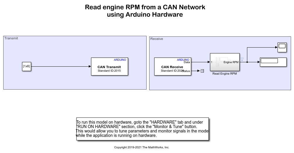
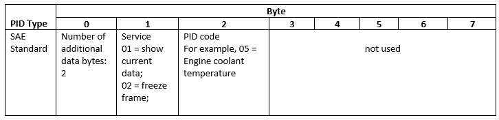
The model contains a Constant block which has a preconfigured Constant value of [2 1 12 0 0 0 0 0]. This value is required to send a request to receive engine RPM details.
Information used in the value [2 1 12 0 0 0 0 0] has a specific usage. The usage and purpose of the value [2 1 12 0 0 0 0 0] is as shown in this table.
Send Request for Engine RPM Using CAN Transmit Block
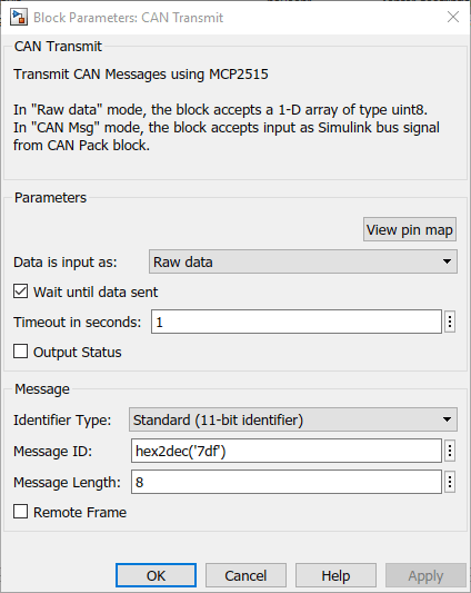
Double-click the CAN Transmit block to open the block mask and set the CAN Transmit block parameters as shown in this image. This sends a request to the engine to send the RPM details. The request is sent to the vehicle on the CAN bus at message ID 7DFh, using 8 data bytes.
Data is input as: Data input type used for transmitting messages. You can change this value, if required.
Identifier Type: Message identifier type. Use Standard (11-bitidentifier) type.
Message ID: Value of message identifier. Specify the value as
hex2dec('7df').
Message Length: Message length, in bytes. Specify the value as
8.
Receive Engine RPM Information in CAN Receive Block
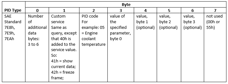
The vehicle responds to the request on the CAN bus at message ID 7E8h. The CAN Receive blocks receives the engine RPM details in the message as shown in this image.
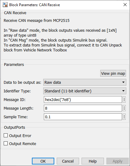
The message hex2dec('7df') received and their usage is as shown in this table.
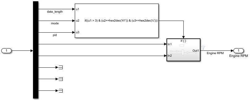
The Scope block displays the data being received in the target hardware. The Read Engine RPM subsystem extracts and validates engine RPM details from the data received.
Deploy Simulink Model
To deploy the Simulink model on your Arduino hardware, on the Hardware tab of the Simulink model, in the Mode section, select Run on board and then click Build, Deploy & Start.
Other things to Try
Working with Arduino CAN blocks in Transmit and Receive Data Using Arduino CAN Blocks example.
You can also select a web site from the following list:
Americas
- América Latina (Español)
- Canada (English)
- United States (English)
Europe
- Belgium (English)
- Denmark (English)
- Deutschland (Deutsch)
- España (Español)
- Finland (English)
- France (Français)
- Ireland (English)
- Italia (Italiano)
- Luxembourg (English)
- Netherlands (English)
- Norway (English)
- Österreich (Deutsch)
- Portugal (English)
- Sweden (English)
- Switzerland
- United Kingdom (English)