Set Jumper Switches
R2026bConfigure the jumpers or switches on the Zynq® SoC or Versal® board so that you can use it as a peripheral device. These jumper settings make it so that the board starts up from the SD card.
The jumper settings are different for each board. To learn more about the settings, see the board documentation.
Hardware Board Setup
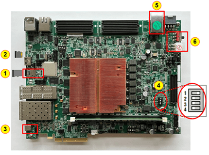
To begin setting up board connection, make sure to:
Plug in the power cord.
Connect the hardware board to the host computer using a JTAG cable if you are using a JTAG connection. A JTAG connection is not supported when you use camera add-on cards.
Connect the hardware board to the host computer using an Ethernet cable if you are using an Ethernet connection.
Insert SD card to the SD card slot.
Connect USB cable to the USB-UART port.
Hardware Configuration
When you make the jumper or switch settings for the board, make sure that the board is turned off. To boot the board the from SD card, make the jumper or switch setting for the respective board as given below.
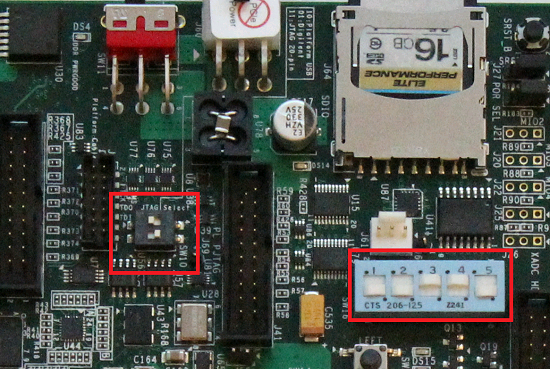
JTAG Select Jumper Positions
| Switch | Switch Position |
|---|---|
| Top | Left |
| Bottom | Right |
SW10 Jumper Positions
| Switch | Switch Position |
|---|---|
| 1 | Down |
| 2 | Down |
| 3 | Up |
| 4 | Up |
| 5 | Down |
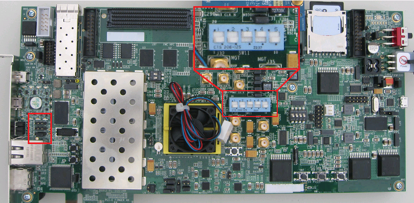
SW11 Jumper Positions
| Switch | Switch Position |
|---|---|
| 1 | Down |
| 2 | Down |
| 3 | Up |
| 4 | Up |
| 5 | Down |
Pins
Set pins 1, 2, and 5 low, and pins 3 and 4 high. The pins are located near the Ethernet LEDs. |
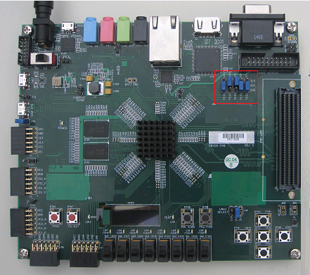
Jumper Positions
| Switch | Switch Position |
|---|---|
| 1 | Down |
| 2 | Up |
| 3 | Up |
| 4 | Down |
| 5 | Down |
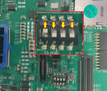
SW6 Switch Positions
| Switch | Switch Position |
|---|---|
| 1 | Up |
| 2 | Down |
| 3 | Down |
| 4 | Down |
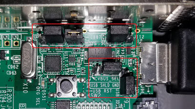
Additional jumper settings are required to connect a USB camera.
Jumper Positions for ZCU102 with USB Camera
| Jumper | Position |
|---|---|
| J7 | connected |
| J109 | connect pins 2 and 3 |
| J110 | connect pins 2 and 3 |
| J112 | connect pins 1 and 2 |
| J113 | connect pins 1 and 2 |
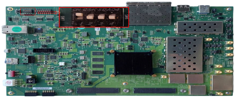
SW6 Switch Positions
| Switch | Switch Position |
|---|---|
| 1 | Up |
| 2 | Down |
| 3 | Down |
| 4 | Down |
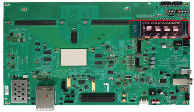
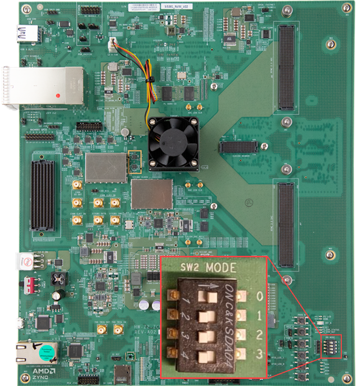
SW2 Switch Positions
| Switch | Switch Position |
|---|---|
| 1 | Up |
| 2 | Down |
| 3 | Down |
| 4 | Down |
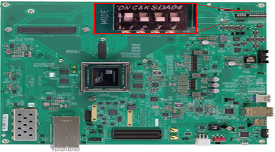
SW2 Switch Positions
| Switch | Switch Position |
|---|---|
| 1 | Up |
| 2 | Down |
| 3 | Down |
| 4 | Down |
SW1 Switch Positions
| Switch | Switch Position |
|---|---|
| 1 | Up |
| 2 | Down |
| 3 | Down |
| 4 | Down |
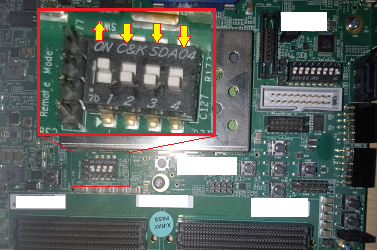
SW6 Switch Positions
| Switch | Switch Position |
|---|---|
| 1 | Up |
| 2 | Down |
| 3 | Down |
| 4 | Down |
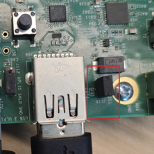
Additional jumper settings are required to connect a USB camera.
Jumper Position for ZCU106 with USB Camera
| Jumper | Position |
|---|---|
| J110 | connected |
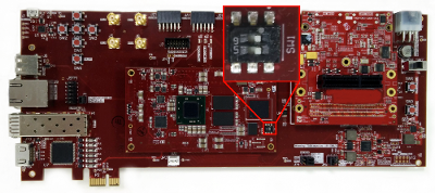
SW1 Switch Positions
| Switch | Switch Position |
|---|---|
| 5 | Right |
| 6 | Right |
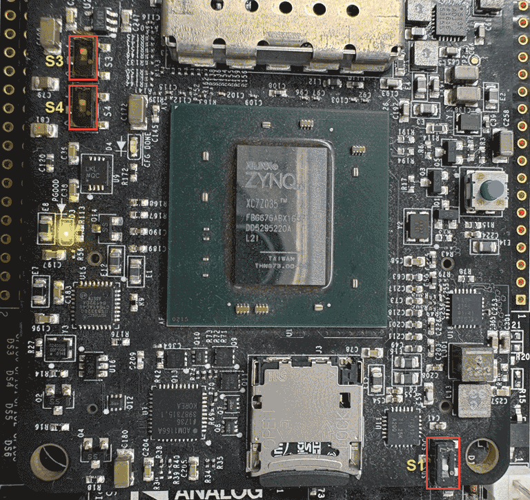
Switch Positions
| Switch | Switch Position |
|---|---|
| S1 | Down |
| S3 | Up |
| S4 | Up |
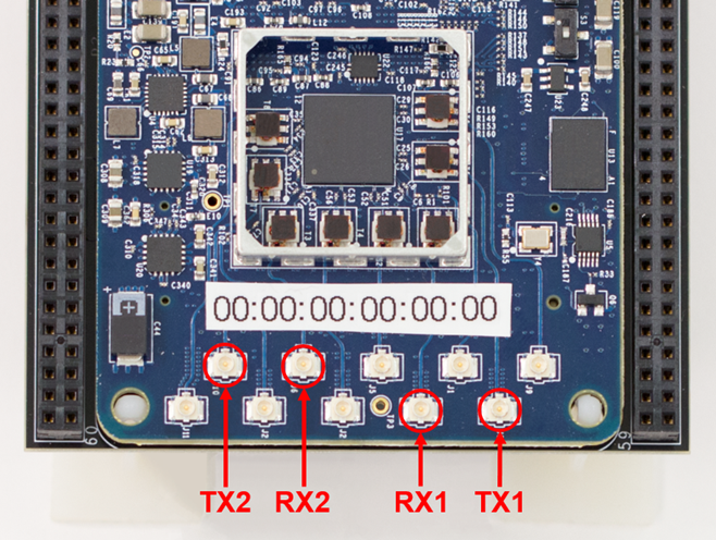
The mapping of port numbers to antennas is as follows:
Jumper Positions for Transmit and Receive Antennas on ADI RF SOM
| Port | Antenna |
|---|---|
| J8 | TX1 |
| J10 | TX2 |
| J4 | RX1 |
| J6 | RX2 |
SW2 Switch Positions
| Switch | Switch Position |
|---|---|
| 1 | Up |
| 2 | Down |
| 3 | Down |
| 4 | Down |
See Also
Install Support for AMD FPGA and SoC Devices | Set Up AMD FPGA and SoC Devices

