Using a Custom Board with SoC Blockset
This example shows how to add the Xilinx® Zynq® UltraScale™+ MPSoC ZCU106 Evaluation Kit to the hardware boards available in the SoC Blockset™. The added board supports the same features as the off-the-shelf SoC Blockset boards.
Introduction
SoC Blockset supports a subset of SoC and FPGA boards. To support custom boards, such as a board with different DDR memory or IO devices, SoC Blockset provides generalized APIs. This example shows how to use these APIs to implement the support for Xilinx Zynq UltraScale+ MPSoC ZCU106 Evaluation Kit.
Supporting a new board requires providing board information in a form that the SoC Blockset features understand. The typical workflow to add board support follows these steps:
Collect board information, which may include certain source files.
Specify board information using board support APIs.
Save board information into hardware information files.
Develop Board Support
1. Collect hardware board information for the Xilinx Zynq UltraScale+ MPSoC ZCU106 Evaluation Kit. Information about GPIO, clock, reset, JTAG chain position, and memory size can be found in the board user guide.
2. Implement the processing system using Vivado® and verify the functionality. Extract Tcl and constraint files from the processing system design. These files are used to generate the FPGA bitstream. A premade Tcl file, ZCU106PS.tcl, is provided with this example.
3. By default device tree blob(DTB) will be generated using device tree information from Linux OS running on the hardware board. Optionally, to generate DTB using device tree files, download premade device tree files from the Analog Devices GitHub repository. Copy zynqmp-zcu106-revA.dts, zynqmp.dtsi, zynqmp-clk.dtsi, and zynqmp-clk-ccf.dtsi to the current working folder. Specify these files in the defineBoardSupportFiles function of the createCustomBoard script included with this example.
4. Specify the hardware board information and features using the board support API as done in createCustomBoard. Run the following MATLAB® function to implement the board support.
boardSupportObj = createCustomBoard;
5. Set up third-party software tools by running the following MATLAB command. The board support can use the same software tools as the reference board support, in this case Board Support for Xilinx Zynq UltraScale+ MPSoC.
soc.sdk.setupSoftwareTools('Zynq ZCU106 Custom SoC Board');
6. Save the current MATLAB path if you want to use the board in different MATLAB sessions.
7. Install the OS image. Download the prebuilt OS image Zip archive from MathWorks GitHub repository. Extract the zip archive onto the microSD card, and insert the card into the hardware board.
8. Set up the Xilinx Zynq UltraScale+ MPSoC ZCU106 Evaluation Kit, and connect it to your host computer using Ethernet.
9. Verify supported features of the board support by running the following MATLAB command. Note that this may take 30 min or longer. In order to verify the deployment features, you need to install Embedded Coder® and HDL Coder™, and add synthesis tool to system path.
test(boardSupportObj);
Use Board Support
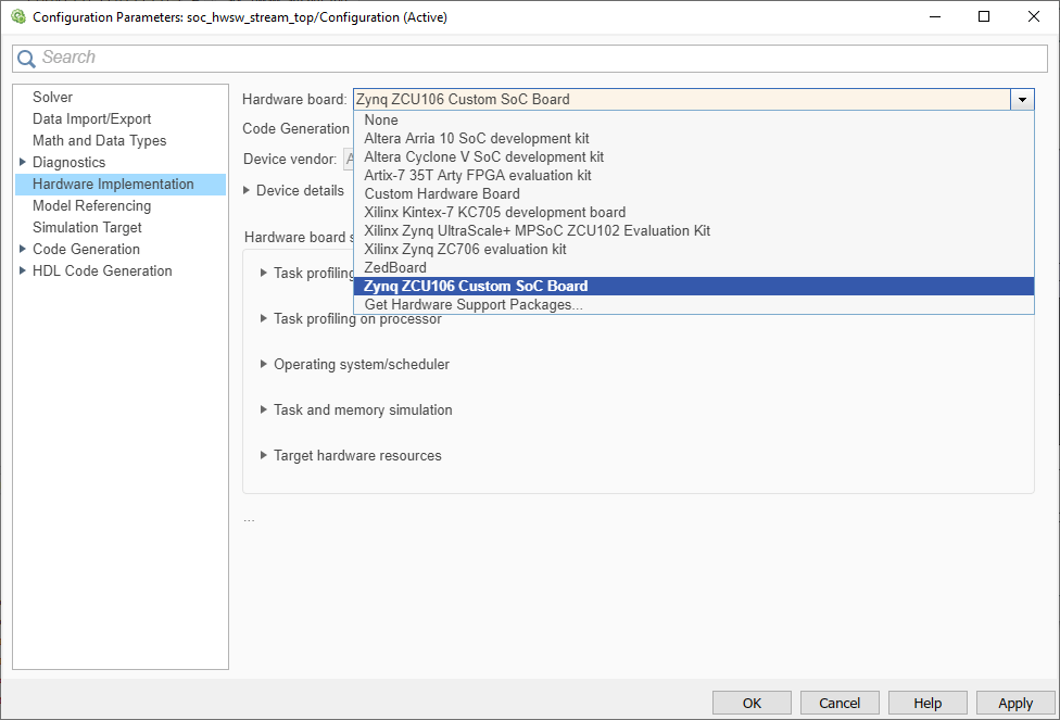
The new hardware board, Zynq ZCU106 Custom SoC Board, can be used with SoC Blockset. For example, you can use this board to implement the Streaming Data from Hardware to Software example. Open the top model soc_hwsw_stream_top. On the System on Chip tab, click Hardware Settings. In the Configuration Parameters dialog box, on the Hardware Implementation tab, select Zynq ZCU106 Custom SoC Board in Hardware board.

Notice that the Hardware board settings are now constrained according to values specified in createCustomBoard. For example, under Target hardware resources > FPGA design (mem controllers), the Controller data width (bits) parameter is set to 128.

The parameter was defined by the following line in createCustomBoard.
procSysObj.SlaveInterfaceDataWidth = 128;
You can now follow the instructions in the Streaming Data from Hardware to Software example to simulate and deploy your model.
Distribute Board Support
If you want to share the new board support, you can package the board support as a MATLAB toolbox. For more information on MATLAB toolboxes, see Create and Share Toolboxes. Run the following command in MATLAB to generate the MLTBX file.
soc.sdk.packageBoardSupport('Board Support for ZCU106');
The MLTBX file is located in the board support folder. It contains the information you provided in the previous section, including any source files.
Install Board Support
To install the board support on another computer, perform the following steps.
1. From the MATLAB Current Folder pane, click the MLTBX file created in the previous step. This creates the board support folder in the MATLAB Add-Ons folder, extracts the board support files, and adds the required folders to the MATLAB path.
2. Register the new board support with SoC Blockset by running the following MATLAB command.
sl_refresh_customizations;
3. Set up third-party software tools by running the following MATLAB command.
soc.sdk.setupSoftwareTools('Zynq ZCU106 Custom SoC Board');
If you want to create an OS image for your board from the kernel source code instead using the prebuilt MathWorks OS image, you can follow these additional steps.
4. Clone or download the Linux kernel source files from Analog Devices(2018_R1 branch) or from MathWorks GitHub repository.
5. Configure and build the kernel using a build system, such as PetaLinux or Buildroot. Make sure that board can be properly booted with the new image.
6. If you are using the kernel source files from Analog Devices, follow OS Customization Workflow to update the required libraries and packages in the OS image using the external build system.
Other Things to Try
You may apply the same workflow to add support for different boards if they are based on the same device family. You may also add the support for the board without processor cores for pure FPGA applications.