Refine, Test, and Debug a Subsystem
This example shows how to refine and test a controller subsystem by using a test harness. Test harnesses provide a development and testing environment that leaves the main model design intact. You can test a functional unit of your model in isolation without altering the main model. In the example, the main model is a controller-plant model of an air conditioning/heat pump unit. The controller must operate according to several requirements.
Open the Model
sltestHeatpumpExample

In the example model:
The controller accepts the room temperature and specified temperature inputs.
The controller output is a bus with signals that control the fan, heat pump, and the direction of the heat pump (heat or cool).
The plant accepts the control bus. The heat pump and the fan signals are Boolean, and the heat pump direction is specified by +1 for cooling and -1 for heating.
Temperature Condition States
The test covers four temperature conditions. Each condition corresponds to one operating state with fan, pump, and pump direction signal outputs.

Create a Harness for the Controller
1. Right-click the Controller subsystem. To add the Simulink Test app options to the menu, point to Select Apps and click Simulink Test. Then, in the Simulink Test app section, click the Add Test Harness button ![]() .
.
2. Set the harness properties in the Basic Properties tab:
Name:
devel_harness1Save test harness externally: not selected
Sources and Sinks:
NoneandScope, respectivelyAdd separate assessment block: not selected.
Open harness after creation: selected

3. Click OK to create the harness.

Inspect and Refine the Controller
1. In the test harness, double-click Controller to open the subsystem.

2. Connect the chart to the Inport blocks.

3. In the test harness, click Save to save the test harness and model.
Add Test Inputs and Test the Controller
1. Navigate to the top level of devel_harness1.
2. Create a test input for the harness with a constant Tset and a time-varying Troom. Connect a Constant block to the Tset input and set the value to 75.
3. Add a Sine Wave block to the harness model to simulate a temperature signal. Connect the Sine Wave block to the conversion subsystem input Troom_in.
4. Double-click the Sine Wave block and set the parameters:
Amplitude: 15
Bias: 75
Frequency: 2*pi/3600
Phase (rad): 0
Sample time: 1
Select Interpret vector parameters as 1–D
5. Connect Inport blocks to the Data Store Write inputs.

6. In the Modeling tab, click Model Settings to open the Configuration Parameters dialog box, in the Data Import/Export pane, select Input and enter u. u is an existing structure in the MATLAB® base workspace. Then, click Apply.
7. In the Solver pane, set Stop time to 3600. Click OK.
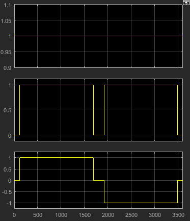
8. Open the Scope in the test harness and change the layout to show three plots.
9. Click Run to simulate.
Debug the Controller
1. Observe that the controller output, fan_cmd, is 1 during the IDLE condition where |Troom - Tset| < DeltaT_fan. This is a bug because fan_cmd should be 0 at IDLE. The fan_cmd control output must be changed for IDLE.
2. In the harness model, open the Controller subsystem.
3. Open controller_chart.
4. In the IDLE state, fan_cmd is set to return 1. Change fan_cmd to return 0. IDLE is now:
IDLE
entry:
fan_cmd = 0;
pump_cmd = 0;
pump_dir = 0;
5. Simulate the harness model again and observe the outputs.
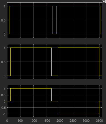
fan_cmd now meets the requirement to equal 0 at IDLE.