Sample Time in Systems and Subsystems
You can describe a system in terms of the dynamics of the signals in the system. In Simulink®, the sample time of a signal indicates when a model element executes to update the signal value. For example, if a signal has a discrete sample time, the block that produces the signal executes only at discrete time points in simulation that are separated by a fixed interval. Blocks that produce signals with continuous sample time execute and provide a new signal value at every time step in the simulation. For more information, see Types of Sample Time.
You can describe systems and subsystems in Simulink models in terms of the sample times those systems and subsystems contain.
Discrete systems contain only discrete sample times.
Continuous systems do not contain any discrete sample times.
Hybrid systems, also called mixed-signal systems, contain a mix of discrete and continuous sample times.
Multirate systems contain multiple sample times.
Multirate systems can be discrete, in which case all sample times in the system are discrete. Multirate systems can also be hybrid, in which case the system contains both discrete and continuous sample times.
Sample Time in Discrete Systems
Discrete systems contain only discrete sample times and often use blocks that implement discrete algorithms. You can simulate discrete systems using either fixed-step or variable-step solvers. Both fixed-step and variable-step solvers consider the discrete sample times in the model when determining or evaluating the step size for simulations.
Variable-step solvers must have a Max step size parameter value that is smaller than or equal to the smallest discrete sample time in the model.
Fixed-step solvers must have a Fixed-step size (fundamental sample time) parameter value that is a common integer divisor of the sample times in the model.
In some cases, a variable-step solver can take fewer time steps in simulations of
multirate discrete systems compared to a fixed-step solver. For example, suppose a
system has two discrete rates: 0.5 and 0.75.
The greatest common integer divisor is 0.25, so a fixed-step
solver simulates the model using a fixed-step size that is less than or equal to
0.25. In this system, some time steps in the fixed-step
simulation, such as the time step at 0.25, do not correspond to a
hit time for either discrete sample time in the system. In contrast, the
variable-step solver must ensure only that the maximum step size is less than or
equal to the smallest discrete rate, 0.5.
For complete information about choosing a solver for simulation, see Choose a Solver.
Sample Time in Multirate and Hybrid Systems
Many systems contain a mix of discrete and continuous components that you model using both continuous and discrete sample times.
Multirate systems contain more than one sample time other than constant sample time and sample times for model-wide events.
For details, see Types of Sample Time.
Hybrid systems contain both continuous and discrete sample times.
You can use the Timing Legend and sample time colors to annotate block diagrams with sample time information. When designing and simulating multirate and hybrid systems, the sample time colors can help you determine whether the systems and subsystems in your model have inherited the desired and expected sample times.
Because both multirate discrete systems and hybrid systems are multirate, the multirate sample time color applies to both multirate discrete systems and hybrid systems. To determine whether a model element highlighted with the multirate sample color is multirate discrete or hybrid, you must look at the surrounding sample time information.
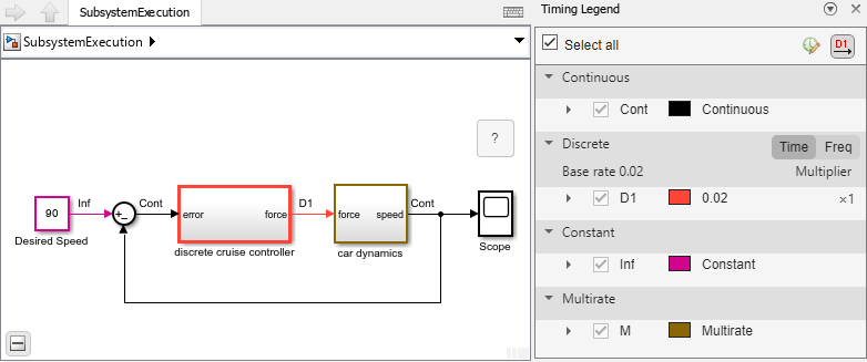
For example, consider this model of a cruise control system for a car, implemented
as a simple feedback loop. A Constant block provides the cruise
control set point. An atomic subsystem named discrete cruise
controller provides the input signal for a virtual subsystem named
car dynamics. The velocity of the car acts as the feedback
signal, which is subtracted from the Constant block output signal to
compute the error input for the discrete cruise controller.

To open the Timing Legend and display the sample time colors, in the
Simulink Toolstrip, on the Debug tab, under
Diagnostics, click Information
Overlays. Then, under Sample Time, select
Colors. To annotate signal lines with sample time
information, in the Timing Legend, click Toggle sample time annotation
display ![]() .
.
The sample time colors highlight the virtual subsystem brown, the default color
for multirate systems. In the block diagram, you can see that the subsystem is a
hybrid multirate system because it has both discrete and continuous sample times.
The input signal is discrete, colored red, and labeled D1, while
the output signal is continuous, colored black, and labeled Cont
for continuous.

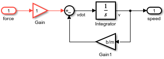
To get more information about the sample times in the hybrid system, navigate
inside the subsystem named car dynamics. The car dynamics are
modeled using an Integrator block, which introduces continuous
dynamics. The sample time colors show that the subsystem contains both discrete and
continuous sample times.

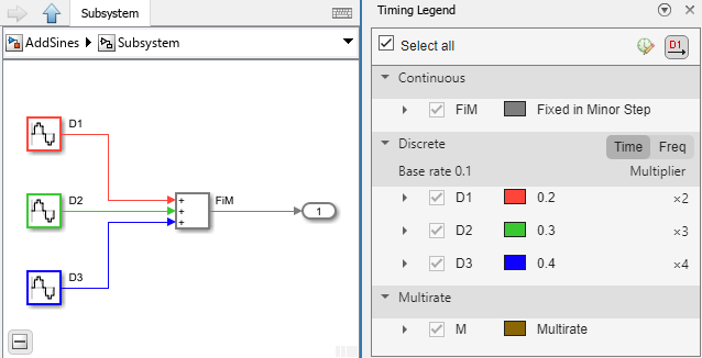
Now consider a different multirate subsystem that has a single output signal labeled with fixed-in-minor (FiM) sample time. The sample time colors also highlight this subsystem with the multirate sample time color to indicate that the subsystem is multirate. To understand the sample times in the subsystem, view the subsystem contents.

The subsystem contains three Sine Wave blocks, each with a
different sample time: 0.2, 0.3, and
0.4. The subsystem is a multirate discrete system because it
contains only discrete sample times.

Sample Time in Subsystems
Subsystems fall into two categories: triggered and non-triggered.
In general, the triggering signal sets the sample time of triggered subsystems.
One exception occurs when you use a Trigger block to create a triggered subsystem and configure the block parameters to activate the Sample time parameter. In this case, the sample time specified for the Trigger block sets the sample time of the subsystem.
The way the software determines the sample time of non-triggered subsystems depends on the type of subsystem.
The software determines the sample times of virtual and enabled subsystems based on the sample times of the subsystem contents.
Atomic subsystems have a Sample time parameter that defines
the sample time of the subsystem. When you specify the sample time of an atomic
subsystem, the sample time of the blocks inside the subsystem must be constant
(Inf), inherited (-1), or the same as the
subsystem sample time. If you leave the default inherited sample time for blocks
inside an atomic subsystem, you can use the Sample time
parameter of the subsystem to specify a discrete sample time for all of the blocks
in the subsystem.
When you leave the default inherited sample time for an atomic subsystem, the
software determines the subsystem sample time based on the sample times of the
subsystem contents, the same as virtual and enabled subsystems. To get the sample
time of an atomic subsystem, use the get_param function. This command
gets the value of the SystemSampleTime parameter of an atomic
subsystem named AtomicSubsystem in a model named
mdl.
st = get_param("mdl/AtomicSubsystem","SystemSampleTime");
The If or Switch Case block inside an action subsystem sets the sample time of an action subsystem.
When a non-triggered subsystem contains blocks with different sample times, the
compiled sample time of the subsystem indicates the sample times in the subsystem.
To get the compiled sample time of a subsystem, use the
get_param function. This command gets the value of the
CompiledSampleTime parameter of a Subsystem
block named Subsystem in a model named mdl. If
the subsystem is a multirate subsystem, the get_param function
returns the compiled sample time as a cell array of character vectors.
st = get_param("mdl/Subsystem","CompiledSampleTime");