Demux
Extract and output elements of virtual vector signal
Libraries:
Simulink /
Commonly Used Blocks
Simulink /
Signal Routing
HDL Coder /
Commonly Used Blocks
HDL Coder /
Signal Routing
Description
The Demux block extracts the components of an input vector signal and outputs separate signals. The output signal ports are ordered from top to bottom.
Examples
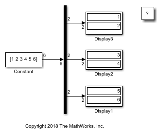
You can use the Demux block to distribute an input signal evenly over the desired number of outputs. For an input vector of length 6, when you set the Number of outputs parameter to 3, the Demux block creates three output signals, each of size 2.
To view this behavior, open and simulate the example model.
mdl = "DemuxVectorUnspecified";
open_system(mdl)
sim(mdl);
When using the Demux block to extract and output elements from a vector input, you can use -1 in a vector expression to indicate that the block dynamically sizes the corresponding port. When a vector expression comprises both positive values and -1 values, the block assigns as many elements as needed to the ports with positive values. The block distributes the remaining elements as evenly as possible over the ports with -1 values.
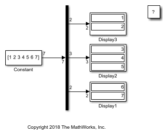
In this example, the Number of outputs parameter of the Demux block is set to [-1, 3, -1]. Thus, the block outputs three signals where the second signal always has three elements. The sizes of the first and third signals depend on the size of the input signal. For an input vector with seven elements, the Demux block outputs two elements on the first port, three elements on the second port, and two elements on the third port.
To view this behavior, open and simulate the example model.
mdl = "DemuxVectorSpecified";
open_system(mdl)
sim(mdl);
Extended Examples
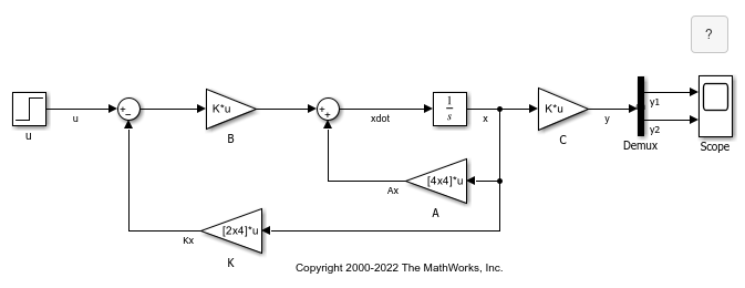
Extract Output Elements of Feedback System
Demonstrates how to extract the output elements of a state-space system that uses vector signals.
Ports
Input
Vector input signal from which the Demux block selects scalar signals or smaller vectors.
Data Types: single | double | half | int8 | int16 | int32 | int64 | uint8 | uint16 | uint32 | uint64 | Boolean | fixed point | enumerated | image
Output
Output signals extracted from the input vector. The output signal ports are ordered from top to bottom. For a description of the port order for various block orientations, see Identify Port Location on Rotated or Flipped Block.
Data Types: single | double | half | int8 | int16 | int32 | int64 | uint8 | uint16 | uint32 | uint64 | Boolean | fixed point | enumerated | image
Parameters
Specify the number of outputs and, optionally, the dimensionality of each output port.
The value can be a scalar specifying the number of outputs or a vector whose elements specify the widths of the block output ports. The block determines the size of its outputs from the size of the input signal and the value of the Number of outputs parameter.
If you specify a scalar for the Number of outputs parameter, and all of the output ports are connected, as you draw a new signal line close to the output side of a Demux block, the software adds a port and updates the Number of outputs parameter.
For an input vector of width n, this table describes what the
block outputs.
| Parameter Value | Block Output | Examples and Comments |
|---|---|---|
|
| If the input is a three-element vector and you specify three outputs, the block outputs three scalar signals. |
| Error | This value is not supported. |
|
| If the input is a six-element vector and you specify three outputs, the block outputs three two-element vectors. |
|
| If the input is a five-element vector and you specify three outputs, the block outputs two two-element vector signals and one scalar signal. |
|
| If the input is a five-element vector and you specify |
An array that has one or more of For example, suppose that you have a four-element
array with a total width of 14 and you specify the parameter to be
The
value for the third element (the |
| If |
| Error | This value is not supported. |
If you specify a number of outputs that is smaller than the number of input elements, the block distributes the elements as evenly as possible over the outputs.
Specifying
a nondouble value, such as single(3), is not
supported.
Programmatic Use
To set the block parameter value programmatically, use
the set_param function.
| Parameter: | Outputs |
| Values: | '2' (default) | scalar in quotes | vector in quotes |
| Data Types: | char | string |
Example: set_param(gcb,'Outputs','4')
By default, the block icon is a solid bar of the block foreground color.
To display the icon as a box containing the block type name, select
none.
Programmatic Use
To set the block parameter value programmatically, use
the set_param function.
| Parameter: | DisplayOption |
| Values: | 'bar' (default) | 'none' |
Example: set_param(gcb,'DisplayOption','none')
Block Characteristics
Data Types |
|
Direct Feedthrough |
|
Multidimensional Signals |
|
Variable-Size Signals |
|
Zero-Crossing Detection |
|
Extended Capabilities
Actual data type or capability support depends on block implementation.
HDL Coder™ provides additional configuration options that affect HDL implementation and synthesized logic.
This block has one default HDL architecture.
| ConstrainedOutputPipeline | Number of registers to place at
the outputs by moving existing delays within your design. Distributed
pipelining does not redistribute these registers. The default is
|
| InputPipeline | Number of input pipeline stages
to insert in the generated code. Distributed pipelining and constrained
output pipelining can move these registers. The default is
|
| OutputPipeline | Number of output pipeline stages
to insert in the generated code. Distributed pipelining and constrained
output pipelining can move these registers. The default is
|
This block supports code generation for complex signals.
PLC Code Generation
Generate Structured Text code using Simulink® PLC Coder™.
Actual data type or capability support depends on block implementation.
Version History
Introduced before R2006a
MATLAB Command
You clicked a link that corresponds to this MATLAB command:
Run the command by entering it in the MATLAB Command Window. Web browsers do not support MATLAB commands.
Select a Web Site
Choose a web site to get translated content where available and see local events and offers. Based on your location, we recommend that you select: .
You can also select a web site from the following list
How to Get Best Site Performance
Select the China site (in Chinese or English) for best site performance. Other MathWorks country sites are not optimized for visits from your location.
Americas
- América Latina (Español)
- Canada (English)
- United States (English)
Europe
- Belgium (English)
- Denmark (English)
- Deutschland (Deutsch)
- España (Español)
- Finland (English)
- France (Français)
- Ireland (English)
- Italia (Italiano)
- Luxembourg (English)
- Netherlands (English)
- Norway (English)
- Österreich (Deutsch)
- Portugal (English)
- Sweden (English)
- Switzerland
- United Kingdom (English)
