Modeling Best Practices
Grounding Rules
This section contains guidelines for using domain-specific reference blocks (such as Electrical Reference, Mechanical Translational Reference, and so on) in Simscape™ diagrams, along with examples of correct and incorrect configurations.
Add reference blocks to your models according to the following rules:
Each Domain Requires at Least One Reference Block
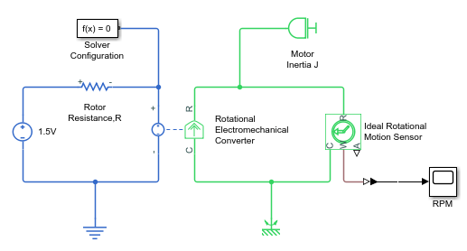
Within a physical network, each domain must contain at least one reference block of the appropriate type. For example, the electromechanical model shown in the following diagram has both Electrical Reference and Mechanical Rotational Reference blocks attached to the appropriate circuits.
Each Circuit Requires at Least One Reference Block
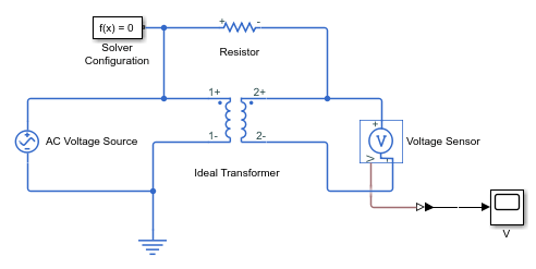
Each topologically distinct circuit within a domain must contain at least one reference block. Some blocks, such as an Ideal Transformer, interface two parts of the network but do not convey information about signal levels relative to the reference block. In the following diagram, there are two separate electrical circuits, and the Electrical Reference blocks are required on both sides of the Ideal Transformer block.

The next diagram would produce an error because it is lacking an electrical reference in the circuit of the secondary winding.

The following diagram, however, will not produce an error because the resistor defines the output voltage relative to the ground reference.
Multiple Connections to the Domain Reference Are Allowed Within a Circuit
More than one reference block may be used within a circuit to define multiple connections to the domain reference:
Electrical conserving ports of all the blocks that are directly connected to ground must be connected to an Electrical Reference block.
All translational ports that are rigidly clamped to the frame (ground) must be connected to a Mechanical Translational Reference block.
All rotational ports that are rigidly clamped to the frame (ground) must be connected to a Mechanical Rotational Reference block.
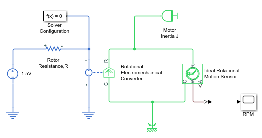
For example, the following diagram correctly indicates two separate connections to an electrical ground.
However, in a position-based translational domain, the Translational World (PB) block represents a single point in space. Therefore, in most situations it is consistent with the physical view to have only one Translational World (PB) block in a connected circuit.
Avoiding Numerical Simulation Issues
Certain configurations of physical modeling blocks can cause numerical difficulties or slow down your simulation. When this happens, Simscape solver issues a warning in the MATLAB® workspace and, if it fails to initialize, a Simscape error.
In electrical circuits, common examples that can cause this behavior include voltage sources connected in parallel with capacitors, inductors connected in series with current sources, voltage sources connected in parallel, and current sources connected in series. Often, the cause of the numerical difficulty is immediately apparent. For example, two voltage sources in parallel must have identical voltage values; otherwise, the ports connecting them would not be physical conserving ports. In practical circuits, topologies such as parallel voltage sources are possible, and small difference in their instantaneous voltages is possible due to parasitic series resistance.
Note
Mathematically, these topologies result in Index-2 differential algebraic equations (DAEs). Their solution requires two differentiations of the constraint equations and, as such, it is numerically better to avoid these component topologies where possible.
There are two approaches to resolving these difficulties. The first is to change the circuit to an equivalent simpler one. In the example of two parallel voltage sources, one source can be simply deleted. The same applies to two series current sources, the deleted one being replaced by a short circuit. For some circuit topologies, however, it is not possible to find an equivalent simpler one that resolves the problem, and the second approach is needed.
The second approach is to include small parasitic resistances in the component. In the Simscape Foundation library, the Capacitor and Inductor blocks include such parasitic terms, so that you can connect capacitances in parallel with voltage sources and inductors in series with current sources. If your circuit does not have any such topologies, then you can change the default parasitic terms to zero. Note that other blocks do not contain these parasitic terms, for example, the Mutual Inductor block. Therefore, if you wanted to connect a mutual inductor primary in series with a current source, you would need to introduce your own parasitic conductance across the primary winding.
Example of Using a Parasitic Resistance to Avoid Numerical Simulation Issues
The following diagram models a differentiator that might be used as part of a Proportional-Integral-Derivative (PID) controller. To open this example model, type:
openExample('simscape/OpAmpCircuitDifferentiatorExample')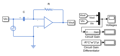
Simulate the model, and you will see that the output is minus the derivative of the input sinusoid.
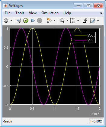
Now double-click the capacitor C block, and set the series resistance to zero. The model now runs very slowly and issues warnings about problems with transient initialization and step size control for transient solve.
The cause of the problems is that the circuit effectively connects the voltage source
in parallel with the capacitor. This is because an ideal op-amp satisfies
V+
=
V- , where V+ and V- are the
noninverting and inverting inputs, respectively. This is an example where it is not
possible to replace the circuit with an equivalent simpler one, and a parasitic small
resistance has to be introduced.