Converter (Three-Phase, DQ0)
R2026bThree-phase bidirectional AC/DC converter in direct-quadrature-zero reference frame
Since R2026b
Converter (Three-Phase, DQ0) block

To add a block to a model, double-click the canvas and start typing the block name. Then, select the block from the list.
Libraries:
Simscape /
Electrical /
DQ0 Components /
Converters
Description
The Converter (Three-Phase, DQ0) block converts electrical power from AC to DC or from DC to AC. The block operates using either a three‑element Vdq0 voltage input or a two‑element Vdq input.
Equations
This equation defines the balance of power in the block:
where:
idc is the DC-link current flowing into the converter.
vdc is the DC-link voltage at the converter DC terminals.
Ploss represents the total power loss in the converter.
is the AC-side power.
vd is the d-axis voltage.
id is the d-axis current.
vq is the q-axis voltage.
iq is the q-axis current.
v0 is the zero-sequence voltage.
i0 is the zero-sequence current.
Parameterize Losses
Switching losses, conduction losses, and quiescent losses are the main heat sources for a converter.
This equation defines the switching losses
where:
ks is the proportionality constant that depends on the turn-on and turn-off intervals and switching frequency. Specify this value by setting the Switching losses coefficient, ks parameter.
vdc is the dc-link voltage.
is the root mean squared (RMS) phase current.
This equation defines the conduction losses
where:
kc1 is the coefficient of the conduction losses that depends on the on-state zero current collector-emitter voltage of the transistor and on the forward voltage drop of the diode. Specify this value by setting the Conduction losses coefficient, kc1 parameter.
kc2 is the coefficient of the conduction losses that depends on the state resistance of the transistor and on the anti-parallel diode. Specify this value by setting the Conduction losses coefficient, kc2 parameter.
The Fixed power loss parameter defines the quiescent losses, Pfixed.
The sum of the switching, conduction, and quiescent losses defines the total power loss of the converter:
If the ks,
kc1,
kc2, and
Pfixed parameters values are not available, then
you can obtain them from the power losses profile instead, by setting the Losses
parameterization parameter to Profile:
loss=f(Irms,vdc_nom). To calculate the values of the parameters, the block
solves the equation
where:
is the vector of power loss values. Specify this vector by using the Converter losses parameter.
vdc_nom is equal to the Nominal dc-link voltage parameter value.
is the vector of root mean square currents associated to the values of the Converter losses parameter. Specify this vector by using the RMS current for converter losses parameter.
Model Thermal Effects
This block has one optional thermal port. To control the visibility of the thermal port, set the Modeling option parameter to either:
No thermal port— The block does not contain a thermal port.Show thermal port— The block contains one thermal conserving port.
Variables
To set the priority and initial target values for the block variables prior to simulation, use the Initial Targets section in the block dialog box or Property Inspector. For more information, see Set Priority and Initial Target for Block Variables.
Nominal values provide a way to specify the expected magnitude of a variable in a model. Using system scaling based on nominal values increases the simulation robustness. Nominal values can come from different sources, one of which is the Nominal Values section in the block dialog box or Property Inspector. For more information, see System Scaling by Nominal Values.
To enable the Initial Targets and Nominal
Values sections in this block, set the Modeling option
parameter to Show thermal port.
Examples
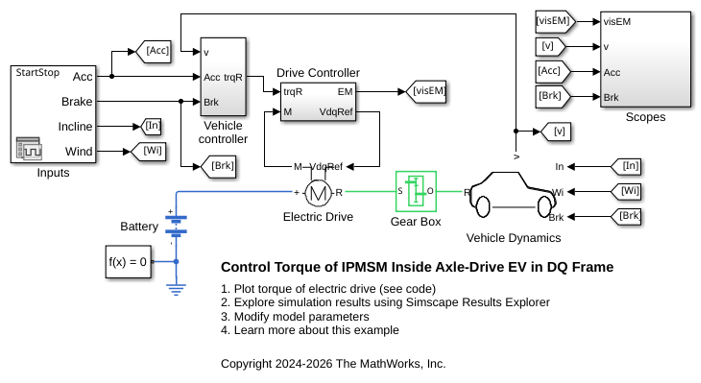
Control Torque of IPMSM Inside Axle-Drive EV in DQ Frame
Models an interior permanent magnet synchronous machine (IPMSM) propelling a simplified axle-drive electric vehicle. The example controls and simulates the torque in the rotor direct-quadrature (DQ) reference frame. The IPMSM operates in both motoring and generating modes. A fixed-ratio gear-reduction model implements the vehicle transmission and differential. The Vehicle Controller subsystem converts the driver inputs into a relevant torque command. The Drive Controller subsystem controls the torque of the IPMSM. The control algorithm is implemented in continuous time. To simulate this model faster, this example uses a variable-step solver. The Scopes subsystem contains scopes that allow you to see the simulation results.
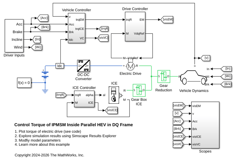
Control Torque of IPMSM Inside Parallel HEV in DQ Frame
Models a simplified parallel hybrid electric vehicle (HEV). An interior permanent magnet synchronous machine (IPMSM) and an internal combustion engine (ICE) provide the vehicle propulsion. This example controls and simulates the torque in the rotor direct-quadrature (DQ) reference frame. The IPMSM operates in both motoring and generating modes. A fixed-ratio gear-reduction model implements the vehicle transmission and differential. The Vehicle Controller subsystem converts the driver inputs into torque commands. A Stateflow® chart implements the vehicle control strategy. The ICE Controller subsystem controls the torque of the combustion engine. The EM Controller subsystem controls the torque of the IPMSM. To simulate this model faster, this example uses a variable-step solver. The Scopes subsystem contains scopes that allow you to see the simulation results.
Assumptions and Limitations
This block defines the dq0 quantities in the synchronous reference frame using the standard power-variant form. For more information about the Park transform, see Park Transform.
Ports
Inputs
Conserving
Parameters
References
[1] Rajput, M. N. Thermal Modeling of Permanent Magnet Synchronous Motor and Inverter. Master’s thesis, Georgia Institute of Technology, 2016.
Extended Capabilities
Version History
Introduced in R2026b

