Tensioner with Custom Belt Pulley Components
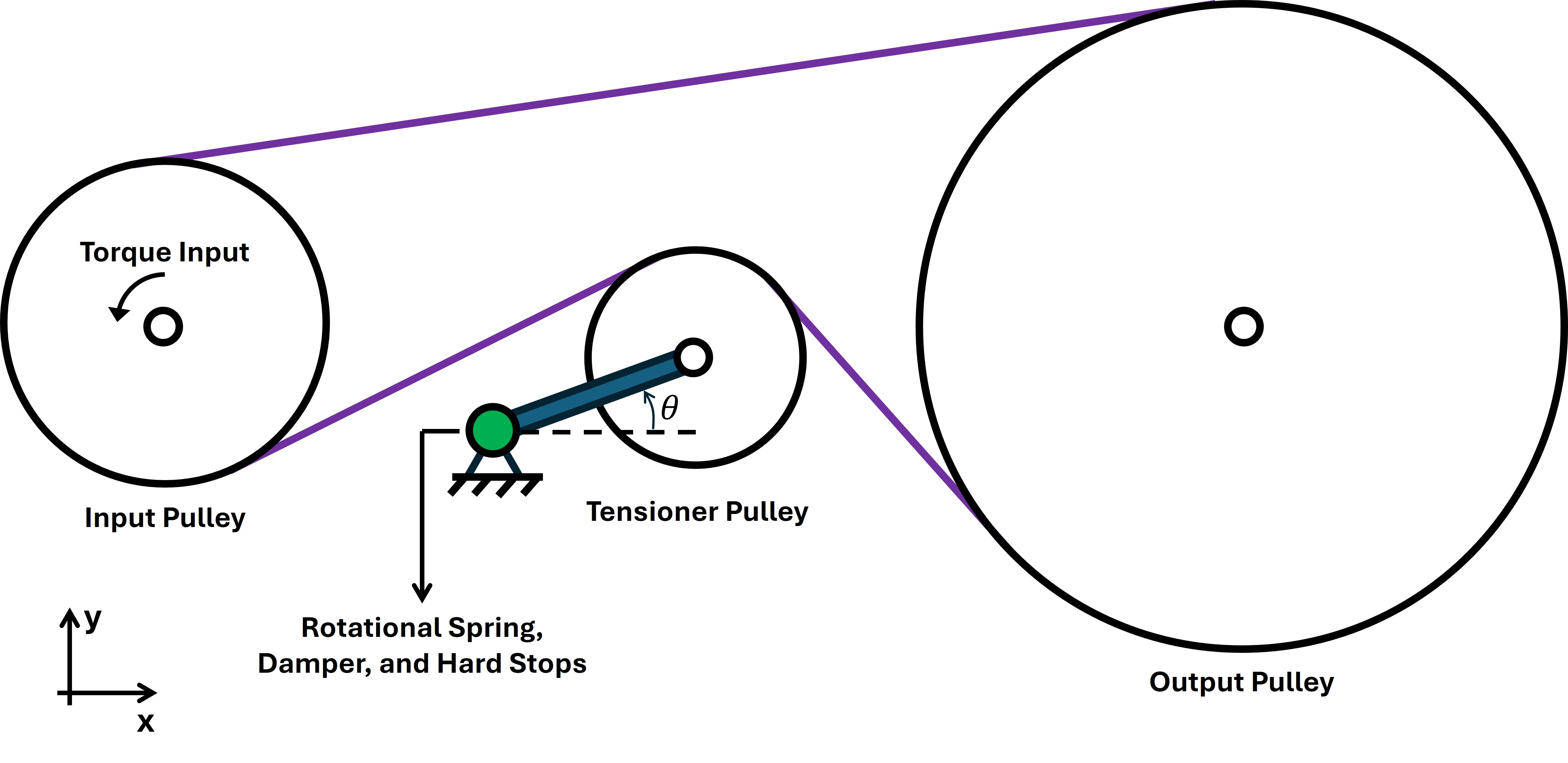
R2026bThis example shows how to model a belt drive with a tensioner by using a custom pulley domain. The custom domain accounts for the two-dimensional kinematics and dynamics of the system. The belt drive contains an input pulley, output pulley, and tensioner, arranged in a two-dimensional space. The input pulley receives a torque from the shaft, and the belt transfers the power to the output pulley. The tensioner has a spring-damper unit that maintains tension in the system.
Configure Belt Drive Model
The model consists of three parts: a belt drive network using the custom belt pulley blocks, a tensioner network based on the angle-based mechanical rotational domain, and a tensioner dynamics subsystem that provides an interface between the belt drive network and the tensioner network. Open the model.
open_system('CustomBeltPulleyLibraryTensioner');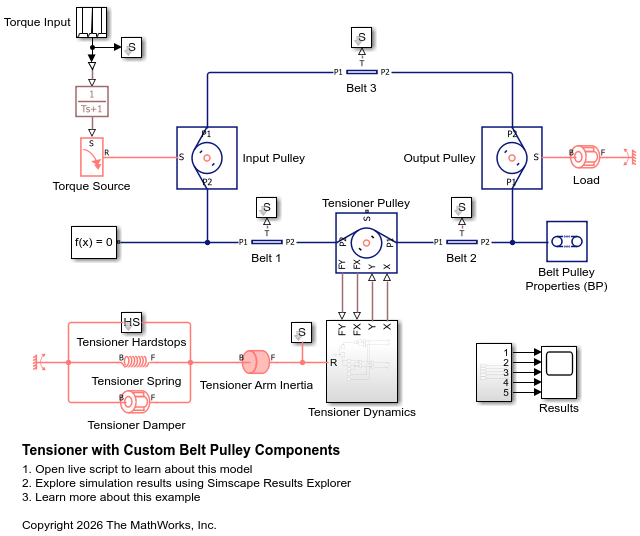
The custom library has four blocks: Belt (BP), Belt (BP-PB), Belt Pulley Properties (BP), and Pulley (BP). A Belt (BP) block provides the connection between two Pulley (BP) blocks. A Belt (BP-PB) block serves as an interface between a Pulley (BP) block and a position-based mechanical translational network. A Belt Pulley Properties (BP) block specifies the domain parameters of the network.
open_system('belt_pulley_lib');
Belt Pulley Properties
Open the Belt Pulley Properties (BP) block and specify the belt density, rigidity, and damping coefficient.
open_system('CustomBeltPulleyLibraryTensioner/Belt Pulley Properties (BP)')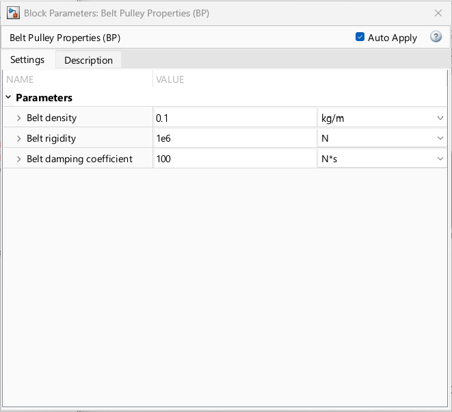
Specify Pulley Positions and Dimensions
The model includes three pulley blocks: Input Pulley, Output Pulley, and Tensioner Pulley. The input and output pulleys are fixed in the two-dimensional space, while the tensioner pulley is able to translate around its pivot. The following table shows the dimensions and coordinates of the pulleys.
Radius of Input Pulley | 0.15 m |
Center Position of Input Pulley (x, y) | (0 m, 0 m) |
Radius of Output Pulley | 0.30 m |
Center Position of Output Pulley (x, y) | (1 m, 0 m) |
Radius of Tensioner Pulley | 0.10 m |
Tensioner pivot position (x, y) | (0.3 m, -0.1 m) |
Tensioner arm length | 0.2 m |
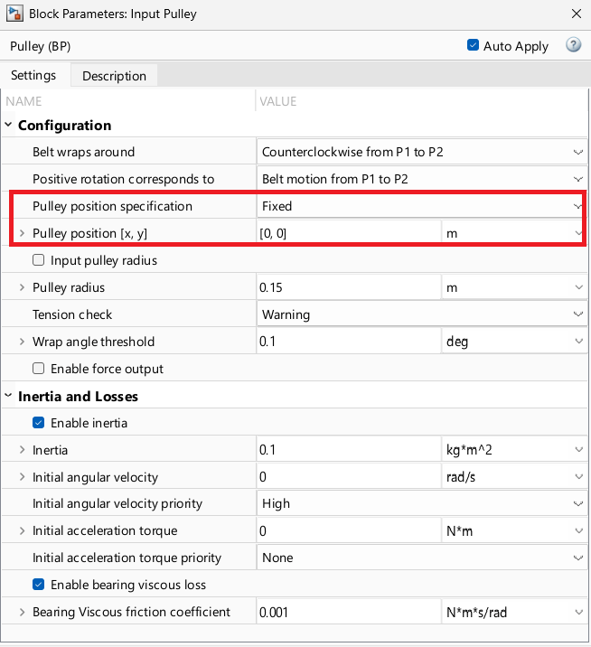
Fix the locations of the input and output pulleys and provide their coordinates. Use the block dialog box for the Input Pulley block to set Pulley position specification to Fixed and Pulley position [x, y] to [0, 0]. For the Output Pulley block, set Pulley position specification and Pulley position [x, y] to Fixed and [1, 0], respectively.
For your convenience, you can enter this code.
% Fix the pulley locations
set_param('CustomBeltPulleyLibraryTensioner/Input Pulley','pulley_position_spec','belt_pulley.enum.PulleyPositionSpec.Fixed');
set_param('CustomBeltPulleyLibraryTensioner/Output Pulley','pulley_position_spec','belt_pulley.enum.PulleyPositionSpec.Fixed');

% Provide the two-dimensional coordinates
set_param('CustomBeltPulleyLibraryTensioner/Input Pulley','position_fixed','[0, 0]');
set_param('CustomBeltPulleyLibraryTensioner/Output Pulley','position_fixed','[1, 0]');
The position of the tensioner pulley is set by the physical signal ports X and Y. To enable these ports, set Pulley position specification to Physical signal, or enter:
set_param('CustomBeltPulleyLibraryTensioner/Tensioner Pulley','pulley_position_spec','belt_pulley.enum.PulleyPositionSpec.PhysicalSignal');
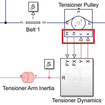
Additionally, enable the FX and FY physical signal outputs to obtain the x- and y-directional forces that are exerted on the shaft by the belt segments, or enter:
set_param('CustomBeltPulleyLibraryTensioner/Tensioner Pulley','enable_force_output','true');
Review Tensioner Dynamics Subsystem
The Tensioner Dynamics subsystem senses the angle of the tensioner, , and then calculates the two-dimensional coordinates of the tensioner pulley. Also, it converts the shaft force to the torque for the Tensioner Arm Inertia block. Note that the Tensioner Arm Inertia block accounts for the inertia of the tensioner body with respect to the pivot point, not the center of the tensioner pulley. To open the Tensioner Dynamics subsystem, enter:
open_system('CustomBeltPulleyLibraryTensioner/Tensioner Dynamics');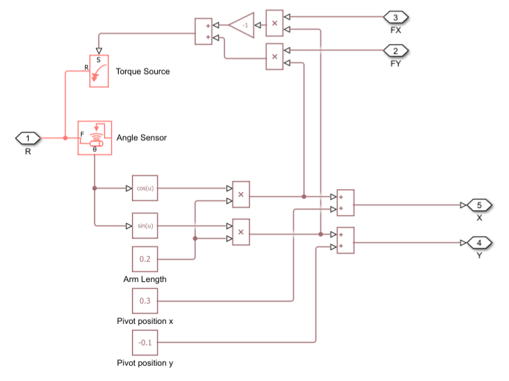
Analyze Results
The model simulates the scenario, according to the simulation time, t.
t = 0.0 - 1.0 s. The system is at rest with no input torque.
t = 1.0 - 2.0 s. The input torque linearly ramps and saturates at 10 N*m.
t = 2.0 - 4.9 s. The system is at steady state with the input torque 10 N*m.
t = 4.9 - 5.1 s. A torque shock occurs. The torque rapidly increases to 100 N*m and then recovers to 10 N*m.
t = 5.1 - 10.0 s. The torque keeps 10 N*m.
All Simscape blocks are in static equilibrium at t = 0 s. The following table shows the high priority initial targets used by the model.
Block | Initial Target | Value |
| Angular velocity Acceleration torque |
|
| Unloaded relative angle |
|
| Angular velocity |
|
| Angular velocity |
|
| Angular velocity |
|
| Belt tension |
|
| Belt tension |
|
| Belt tension |
|
Since the initial tensions are equal everywhere, all pulleys experience zero initial net torque.
To view the results, enter:
open_system('CustomBeltPulleyLibraryTensioner/Results');
sim('CustomBeltPulleyLibraryTensioner');
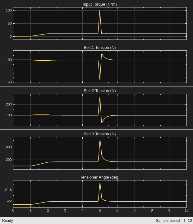
The input torque causes the belt to travel counterclockwise across the pulley network on the canvas. The torque shock occurs at t = 4.9 s, reaching a maximum value of 100 N·m at t = 5 s and recovering to 10 N·m at t = 5.1 s. No belts lose their tension during the shock due to the presence of the tensioner. The torque shock tends to create slack in Belt 1. However, the tensioner moves inward to take up the excess length and prevent slack from forming.

