Generate Global Variables from Signals in Model
R2026bIn IEC61131-3 code, VAR_GLOBAL global variables share data between
the function blocks, programs, and tasks that run on the same controller or across
controllers in a networked architecture. Common use cases for global variables include:
Heartbeat detection systems that monitor health by exchanging counters
Independent control programs on the same PLC that share setpoint and status values
Safety and process function blocks that read shared interlock flags
In Simulink®, you can create global variables by using
Simulink.Signal objects and the Data Store Memory
block.
Generate Global Variables by Using Simulink.Signal
Objects
To generate global variables in your code, use a global Data Store Memory block
and a Simulink.Signal object. To generate global variables:
Add a Data Store Memory block to your top-level model. If you add a Data Store Memory block inside a subsystem, Simulink PLC Coder™ generates the variables as local variables.
Associate a
Simulink.Signalobject with the Data Store Memory block. To associate the signal:Create a
Simulink.Signalobject with the same name as the data store in the base workspace. Set the storage class of the object toExportedGlobalorImportedExtern.Enable the Data store name must resolve to Simulink signal object parameter of the Data Store Memory block by using the Model Data Editor. In the Modeling tab, in the Design section, select Model Data Editor. In the Model Data Editor window, in the Data Stores tab, select the Resolve check box for the Data Store Memory block.
To use Data Store Read and Data Store Write blocks, set the Data store name block property of these blocks to the signal name.
If you generate code for the Rockwell Automation® RSLogix 5000 or Studio 5000 IDEs, the
Simulink.Signal object appears as an INOUT
variable in the generated Structured Text Code. If you generate code for other IDEs,
the storage class of the Simulink.Signal object determines how the
Simulink.Signal object appears in the generated Structured
Text Code:
| Storage Class | Variables in Generated Code |
|---|---|
ExportedGlobal | The Simulink.Signal object is a
VAR_GLOBAL variable that has
initialization. |
ImportedExtern | The Simulink.Signal object is referenced in
the generated code. You must define the variable externally. |
PLC Heartbeat Counter Detection Using Global Variables
This example shows how to model a PLC heartbeat counter detection system by using global variables and generate Structured Text code for the heartbeat detection subsystem. When multiple PLC programs on the same controller or across controllers in a network, must share data they use a heartbeat counter to synchronize the data. To synchronize the data between the two PLC's, you can use a free running counter and global variables. Each PLC maintains a free-running counter and shares the counter data with other PLC's by using the global variable.
In this example, you:
Define global variables by using Data Store Memory blocks and
Simulink.Signalobjects.Set up externally defined identifiers for variables owned by another PLC program
Generate IEC 61131-3 Structured Text code with
VAR_GLOBALdeclarations and external references
Open and Examine the Model
Open the model.
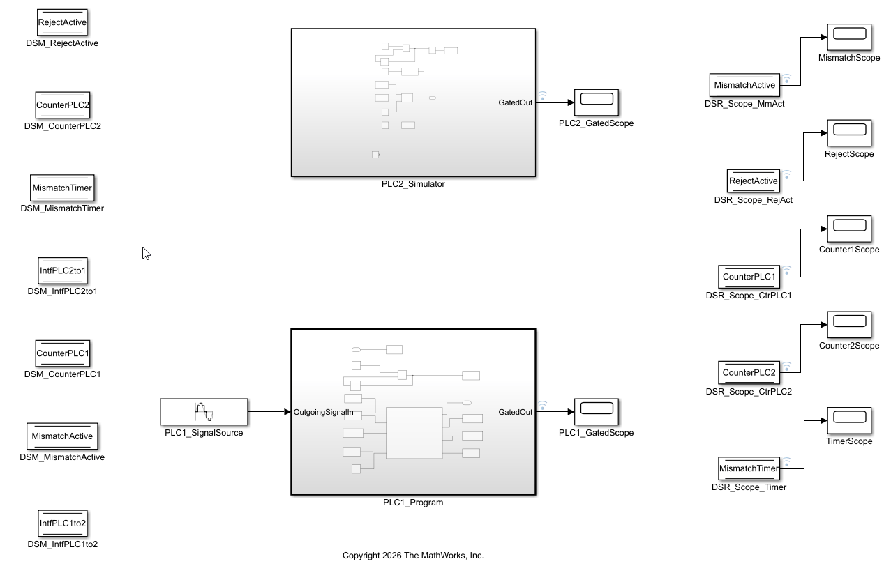
open_system("CounterMismatchPLC.slx")The model contains two subsystems:
The
PLC1_Programsubsystem that models the PLC1 counter logic, mismatch detection system, and signal gating. It contains Data Store Read blocks to read the data from thePLC2_Simulatorsubsystem and Data Store Write blocks to write data to thePLC2_Simulatorsubsystem.The
PLC2_Simulatorsubsystem that models the PLC2 counter logic, a Step block to add a value to the counter, a Data Store Read block to read signals from thePLC1_Programsubsystem, and Data Store Write blocks to write data to thePLC1_Programsubsystem.
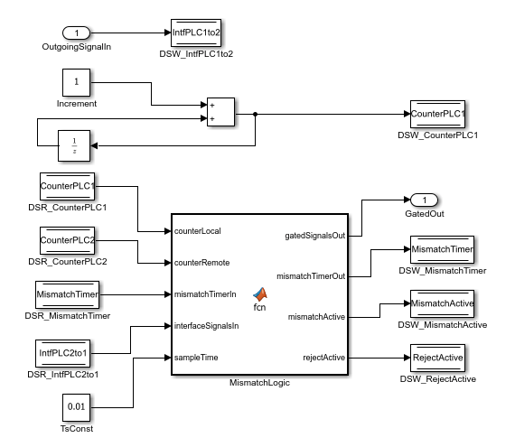
The PLC1_Program subsystem generates the PLC1 free-running counter signal CounterPLC1, interface signal IntfPLC1to2, reads the PLC2 counter signal CounterPLC2, compare the PLC1 and PLC2 counters, and generate the data synchronization signals MismatchActive and RejectActive.
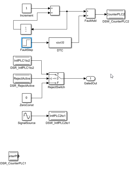
The PLC2_Simulation subsystem generates the PLC2 free-running counter signal CounterPLC2 and data for the IntfPLC2to1 signal. It contains a Step block to add an additional value to the CounterPLC2 signal, a Switch block that switches the output based on the RejectActive signal.
The PLC1_Program subsystem is the code generation target. When you generate code, Simulink PLC Coder generates global variables for each simulink.Signal object that uses the ExportedGlobal storage class. Because the PLC2_Simulation subsystem signals CounterPLC2 and IntfPLC2to1 use the storage class ImportedExtern, and are inputs to the PLC1_Program subsystem, you must define these signals when you import the generated code into your target IDE. This table shows the Simulink.Signal objects in this model, their storage classes, and their variable type in the generated code.
Variable | Storage Class | Variable Type in Generated Code | Variable Initialized |
|
|
| Yes |
|
|
| Yes |
|
|
| Yes |
|
|
| Yes |
|
|
| Yes |
|
| Not generated. Variable referenced in generated code. You must generate the variable declaration. | No |
|
| Not generated. Variable referenced in the generated code. You must generate the variable declaration. | No |
Define Global Variables
To define global variables, you must create a Simulink.Signal object in the base workspace, set the signal storage class for the object, add a Data Store Memory block in the top-level model, and resolve each Data Store Memory block to its corresponding Simulink.Signal object. You can resolve Data Store Memory blocks to Simulink.Signal objects by either:
Programmatically setting the
StateMustResolveToSignalObjectproperty to on. For example,
set_param("CounterMismatchPLC/DSM_RejectActive", StateMustResolveToSignalObject = "on");
Enabling the Data store name must resolve to Simulink signal object parameter of the Data Store Memory block by using the Model Data Editor. To use the Model Data Editor in a model, on the Modeling tab, in the Design section, select Model Data Editor. On the Data Stores tab, set Change View to
Designand enable Resolve for the Data Store Memory block. For more information, see Model Data Editor.
For example, in this model the DSM_Counter1 block connects to the CounterPLC1 signal and has the StateMustResolveToSignalObject property set to on. The CounterPLC1 signal has storage class ExportedGlobal.
get_param("CounterMismatchPLC/DSM_CounterPLC1","DataStoreName")
ans =
'CounterPLC1'
get_param("CounterMismatchPLC/DSM_CounterPLC1","StateMustResolveToSignalObject")
ans =
'on'
CounterPLC1.CoderInfo.StorageClass
ans =
'ExportedGlobal'
In this example, the model PreLoadFcn callback defines the Simulink.Signal objects and sets their storage class. When you generate code for the PLC1_Program subsystem, Simulink PLC Coder generates the Simulink.Signal objects with storage class ExportedGlobal as global variables.
Remove Initialization Statements
To prevent the generation of initialization statements for externally defined variables, enable the Remove initialization statements for externally defined state variables parameter. For more information, see Remove Initialization Statements for Externally Defined State Variables. You can prevent initialization statements by either:
Programmatically enabling the
PLC_PreventExternalVarInitializationproperty. For example,
cs = getActiveConfigSet("CounterMismatchPLC")
set_param(cs,"PLC_PreventExternalVarInitialization","on")
Enabling the Remove initialization statements for externally defined state variables PLC code generation parameter. Open the PLC Coder app and in the PLC Code tab, click Settings. In the Configuration Parameters dialog box, click PLC Code Generation > Interface and enable Remove initialization statements for externally defined state variables.
Simulate and Inject Faults
The PLC2_Simulator subsystem generates a counter value mismatch by adding a value to the CounterPLC2 signal by using a Step block. When there is a mismatch in the counter values for more than 5 seconds, the RejectActive signal goes True and the Switch block sets the output of the block to zero. You can modify the Step block to test different fault scenarios without modifying the PLC1_Program subsystem. To simulate the system and inject faults, run the run_counter_mismatch_tests.m file.
run_counter_mismatch_tests
===================================================================
  COUNTER MISMATCH PLC - SIMULATION & FAULT INJECTION TEST SUITE
===================================================================
  Code generation target : CounterMismatchPLC/PLC1_Program (atomic)
  Fault injection target : CounterMismatchPLC/PLC2_Simulator/FaultStep

Configuring signal logging...

--- TEST 1: Baseline (No Fault) ---
  Atomic subsystem PLC1_Program should pass all signals.
  Counters within tolerance : true (max diff = 1)
  Max timer value           : 0.0000 s (expected: 0)
  Reject ever active        : false (expected: false)
  RESULT                    : PASS

--- TEST 2: Default Fault (+5 at t=10s) ---
  Fault in PLC2_Simulator → detected by atomic PLC1_Program.
  Mismatch starts at    : 10.01 s (expected: ~10.0)
  Rejection starts at   : 15.01 s (expected: ~15.0)
  Signals zeroed after  : true
  Signals active before : true
  RESULT                : PASS

--- TEST 3: Early Fault (+3 at t=2s) ---
  Mismatch starts at    : 2.01 s (expected: ~2.0)
  Rejection starts at   : 7.01 s (expected: ~7.0)
  RESULT                : PASS

--- TEST 4: Large Offset (+1000 at t=10s) ---
  Rejection starts at   : 15.01 s (expected: ~15.0)
  RESULT                : PASS

--- TEST 5: Transient Fault (recovers at t=13, before timeout) ---
  Max timer value       : 3.00 s (expected: ~3.0, < 5.0)
  Reject after recovery : false (expected: false)
  Timer at t=20         : 0.00 (expected: 0)
  RESULT                : PASS

--- TEST 6: DSM Cross-Visibility (Atomic ↔ Non-Atomic) ---
  Counters within tolerance : true (max diff = 1)
  PLC1 counter (atomic)     : growing = true, final = 1000
  PLC2 counter (harness)    : growing = true, final = 1001
  RESULT                    : PASS

Generating plots...
===================================================================
  TEST REPORT
===================================================================
  Test Name                                      Result
  ---------------------------------------------  ------
  Baseline (No Fault)                            PASS
  Default Fault (+5 at t=10)                     PASS
  Early Fault (+3 at t=2)                        PASS
  Large Offset (+1000 at t=10)                   PASS
  Transient Fault (recovers at t=13)             PASS
  DSM Cross-Visibility                           PASS
  ---------------------------------------------  ------
  Total: 6 passed, 0 failed out of 6
===================================================================

  ALL TESTS PASSED

NEXT STEPS:
  1. Open model:     open_system('CounterMismatchPLC')
  2. Inspect atomic: open_system('CounterMismatchPLC/PLC1_Program')
  3. Generate ST:    plcgeneratecode('CounterMismatchPLC/PLC1_Program')
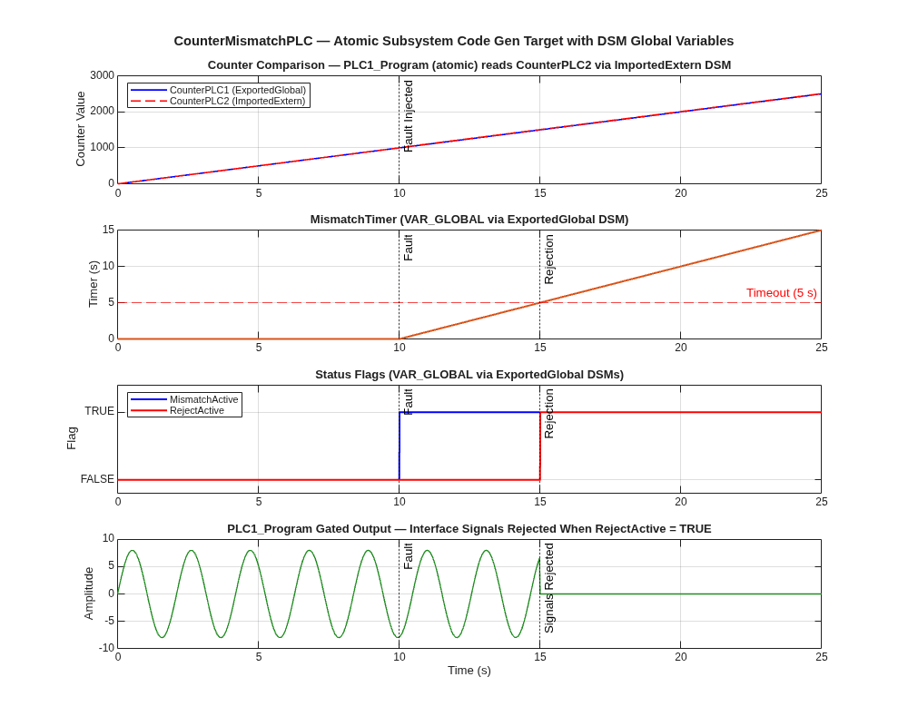
Running the test harness generates a four-panel plot:
TheCounter Comparison plot shows theCounterPLC1andCounterPLC2signals over time. Both lines overlap for the first ten seconds of the simulation. After ten seconds the Step block in thePLC2_Simulationsubsystem add a value of five to theCounterPLC2signal. The atomicPLC1_programsubsystem readsCounterPLC2through a Data Store Read block.The MismatchTimer plot shows the
MismatchTimervariable. This variable ramps from 0 to 5 seconds after the fault. A horizontal line marks the 5 second threshold. The timer crosses it at t = 15 seconds. If the counters agree again before the threshold, the timer resets to zero.The Status Flags plot shows the
MismatchActiveandRejectActivesignals. The signal becomes true at t = 10 seconds andRejectActivebecomes true at t = 15 seconds.The PLC1_Program Gated Output plot shows the interface signal output from the
PLC1_Programsubsystem. The sine wave passes through from zero to 15 seconds and then drops to zero when theRejectActivesignal becomes TRUE.
Generate Structured Text Code
To generate code, select the PLC1_Program subsystem and, in the Apps tab, select PLC Coder. In the PLC Code tab, click Settings. In the Configuration Parameters dialog box, click PLC Code Generation Settings. Change the Target IDE parameter to CODESYS 3.5. Click OK. Click Generate PLC Code.
Alternatively, you can generate code by using the plcgeneratecode function.
open_system("CounterMismatchPLC.slx");
plcgeneratecode("CounterMismatchPLC/PLC1_Program")
### Generating PLC code for 'CounterMismatchPLC/PLC1_Program'.
### Using model settings from 'CounterMismatchPLC' for PLC code generation parameters.
### Begin code generation for IDE CODESYS 3.5 (codesys35).
### Emit PLC code to file.
### Creating PLC code generation report index.html.
### PLC code generation successful for 'CounterMismatchPLC/PLC1_Program'.
### Generated files:
plcsrc/CounterMismatchPLC.xml
View the generated Structured Text code for the PLC1_Program subsystem and view the generated global variables. Simulink PLC Coder generates Simulink.Signal objects that have the storage class ExportedGlobal as VAR_GLOBAL variables and does not generate variables for the Simulink.Signal objects that have the storage class InportedExtern. You must create the variables CounterPLC2 and IntfPLC2to1 when you import the generated code into your target IDE.
file = fullfile("plcsrc/CounterMismatchPLC.xml");
coder.example.extractLines(file,"GVL_VARS","</globalVars>",1,1)
      <globalVars name="GVL_VARS">
        <variable name="MismatchTimer">
          <type>
            <derived name="LREAL"/>
          </type>
        </variable>
        <variable name="IntfPLC1to2">
          <type>
            <derived name="LREAL"/>
          </type>
        </variable>
        <variable name="CounterPLC1">
          <type>
            <derived name="UDINT"/>
          </type>
        </variable>
        <variable name="MismatchActive">
          <type>
            <derived name="BOOL"/>
          </type>
        </variable>
        <variable name="RejectActive">
          <type>
            <derived name="BOOL"/>
          </type>
        </variable>
      </globalVars>
In the generated code, the variables CounterPLC2 and IntfPLC2to1 are not initialized.
coder.example.extractLines(file,"SS_INITIALIZE","SS_STEP",1,0)
    SS_INITIALIZE:
        (* Start for DataStoreMemory: '<Root>/_DataStoreBlk_1' *)
        CounterPLC1 := 0;
        (* Start for DataStoreMemory: '<Root>/_DataStoreBlk_3' *)
        IntfPLC1to2 := 0.0;
        (* Start for DataStoreMemory: '<Root>/_DataStoreBlk_5' *)
        MismatchTimer := 0.0;
        (* Start for DataStoreMemory: '<Root>/_DataStoreBlk_6' *)
        MismatchActive := FALSE;
        (* Start for DataStoreMemory: '<Root>/_DataStoreBlk_7' *)
        RejectActive := FALSE;
        (* SystemInitialize for Atomic SubSystem: '<Root>/PLC1_Program' *)
        (* InitializeConditions for UnitDelay: '<S1>/UnitDelay' *)
        UnitDelay_DSTATE := 0;
        (* End of SystemInitialize for SubSystem: '<Root>/PLC1_Program' *)
See Also
Blocks
Model Settings
- Externally Defined Identifiers | Remove Initialization Statements for Externally Defined State Variables

