Main Content

PWM Reference Generator

Generate modulation signals, duty cycles, and phase voltages from reference voltages based on modulation method

Libraries:
Motor Control Blockset / Controls / Math Transforms
Motor Control Blockset HDL Support / Controls / Math Transforms

Description

The PWM Reference Generator block generates modulation signals, duty cycles, and phase voltages from reference voltages based on selected modulation method. The block provides an option to limit its output which can be used to achieve simplified overmodulation or prevent erratic switching behavior.

The block accepts either the phase voltages (Vabc) or the stator reference voltages (Vαβ) described by the α-β voltage components.

The block supports both the SI unit and per-unit (PU) systems (see Per-Unit System for more details).

Use this block to perform sinusoidal PWM (SPWM) and space vector modulation (SVM) along with these discrete pulse-width modulation (DPWM) methods that reduce switching losses:

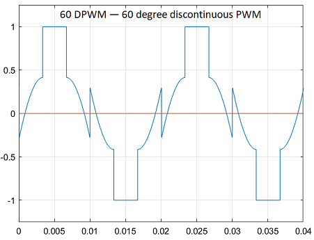
  • 60 DPWM — 60 degree discontinuous PWM

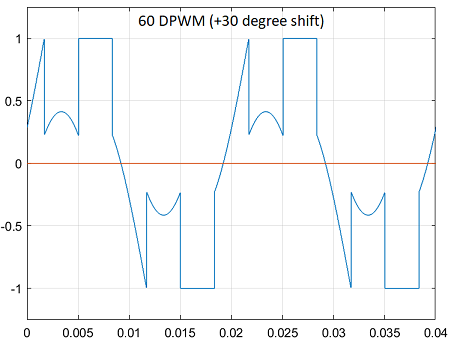
  • 60 DPWM (+30 degree shift) — +30 degree shift from 60 DPWM

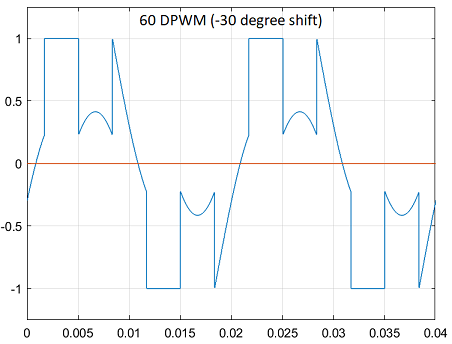
  • 60 DPWM (-30 degree shift) — -30 degree shift from 60 DPWM

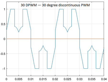
  • 30 DPWM — 30 degree discontinuous PWM

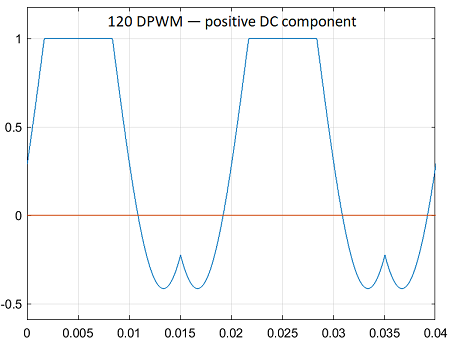
  • 120 DPWM — Positive DC component

  • 120 DPWM — Negative DC component

For discontinuous PWM (DPWM), the block clamps the modulation wave to the positive or negative DC rail for a total of 120 degrees during each fundamental period per phase. During each clamping interval, the modulation discontinues.

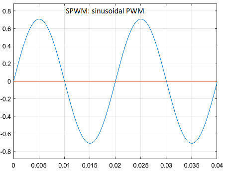
The figure shows the sinusoidal PWM (SPWM) waveform.

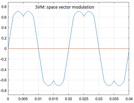
The figure shows the space vector modulation (SVM) waveform.

The figure shows a 60-degree DPWM waveform with two 60-degree clamped intervals per fundamental period.

The figure shows a 60-degree DPWM waveform with a positive 30-degree phase shift.

The figure shows a 60-degree DPWM waveform with a negative 30-degree phase shift.

The figure shows a 30-degree DPWM waveform with four 30-degree clamped intervals per fundamental period.

The figure shows a 120-degree DPWM waveform with positive DC clamping.

The figure shows a 120-degree DPWM waveform with negative DC clamping.

Examples

Ports

Input

expand all

Stator reference voltage component along α-axis of the αβ reference frame.

Dependencies

To enable this port, set Input type to Valphabeta and select the Expand voltage input parameter..

Data Types: single | double | fixed point

Stator reference voltage component along β-axis of the αβ reference frame.

Dependencies

To enable this port, set Input type to Valphabeta and select the Expand voltage input parameter..

Data Types: single | double | fixed point

Single vector signal for αβ stator reference voltage.

Dependencies

To enable this port, set Voltage input type to Valphabeta and clear the Expand voltage input parameter.

Data Types: single | double | fixed point

Component of the three-phase system in the abc reference frame.

Dependencies

To enable this port, set Input type to Vabc and select the Expand voltage input parameter..

Data Types: single | double | fixed point

Component of the three-phase system in the abc reference frame.

Dependencies

To enable this port, set Input type to Vabc and select the Expand voltage input parameter..

Data Types: single | double | fixed point

Component of the three-phase system in the abc reference frame.

Dependencies

To enable this port, set Input type to Vabc and select the Expand voltage input parameter..

Data Types: single | double | fixed point

Single vector representing the three-phase system voltage in the abc reference frame.

Dependencies

To enable this port, set Voltage input type to Vabc and clear the Expand voltage input parameter.

Data Types: single | double | fixed point

Variable DC bus voltage (in volts).

Dependencies

To enable this port, set Input units parameter to SI unit

Data Types: single | double | fixed point

Output

expand all

Output inverter pole voltage component along a-axis of the abc reference frame.

Dependencies

To enable this port, select the Voltage (a,b,c) parameter and select the Expand outputs parameter

Data Types: single | double | fixed point

Output inverter pole voltage component along b-axis of the abc reference frame.

Dependencies

To enable this port, select the Voltage (a,b,c) parameter and select the Expand outputs parameter

Data Types: single | double | fixed point

Output inverter pole voltage component along c-axis of the abc reference frame.

Dependencies

To enable this port, select the Voltage (a,b,c) parameter and select the Expand outputs parameter

Data Types: single | double | fixed point

Single vector representing output inverter pole voltage in abc reference frame.

Dependencies

To enable this port, select the Voltage (a,b,c) parameter and clear the Expand outputs parameter

Data Types: single | double | fixed point

Modulation signal for abc stator reference voltage.

Data Types: single | double | fixed point

Duty cycle for abc stator reference voltage.

Data Types: single | double | fixed point

Parameters

expand all

Parameters

Pulse-width modulation (PWM) method that the block uses to modulate the input stator phase or reference voltages.

Type of three-phase stator voltage representation that the block uses as input. Select either the abc or αβ reference frame.

Option to expand input voltage to its reference components (abc reference frame or αβ reference frame).

Unit of input voltages used in the block. See Per-Unit System for more details.

Note

When the input units are set to Per-unit, the block introduces a gain of 23[VoutVin] when SVM or any DPWM method is selected.

Option to limit the modulation signal in the [-1,1] range.

Dependencies

This parameter is configurable only if you select Per-unit for the Input units parameter.

Outputs

Option to show voltage ( abc reference frame) as output port.

Option to show instantaneous modulation signal ( abc reference frame) as output port.

Option to show PWM duty cycle ( abc reference frame) as output port.

Option to expand output voltage to its phase components (abc reference frame).

Extended Capabilities

expand all

C/C++ Code Generation
Generate C and C++ code using Simulink® Coder™.

Fixed-Point Conversion
Design and simulate fixed-point systems using Fixed-Point Designer™.

Version History

Introduced in R2020a