Effect of Inter-Cell Interference on PDSCH Throughput with MMSE-IRC Receiver
This example demonstrates the effect of inter-cell interference on PDSCH throughput with minimum mean squared error (MMSE) and minimum mean squared error - interference rejection combining (MMSE-IRC) receiver. A serving cell and two interfering eNodeBs are considered. The conditions specified in TS 36.101, Section 8.2.1.4.1B [1] are used.
Introduction
This example measures the achieved throughput for a user equipment (UE) in the serving cell with inter-cell interference from two dominant interfering cells. The serving cell uses RMC R.47 in FDD mode. The parameters for the serving and interfering cells including power levels and noise levels are described in TS 36.101, Section 8.2.1.4.1B [1].
Simulation Settings
The default simulation length is set to four frames to keep the simulation time low. Increase NFrames to increase the simulation time and produce statistically significant throughput results. Use the variable eqMethod to set the receiver equalization.
NFrames =4; eqMethod =
'MMSE_IRC';
The signal, interferers, and noise power levels are specified in the test (TS 36.101, Section 8.2.1.4.1B [1]) using the following parameters: signal-to-interference-plus-noise ratio (SINR), dominant interferer proportion (DIP) and noise power spectral density.
SINR =0.8; % SINR in dB DIP2 =
-1.73; % DIP in dB for cell 2 DIP3 =
-8.66; % DIP in dB for cell 3 Noc =
-98; % dBm/15kHz average power spectral density
The DIP characterizes each of the interfering cells and is defined as:
where and are the average received power spectral density from cells 2 and 3, respectively. is the average power spectral density of a white noise source. The average power for , , and is per resource element normalized with respect to the subcarrier spacing.
Serving eNodeB Configuration
The test considered uses reference channel R.47 in FDD mode. The parameters associated with this reference channel are specified in (TS 36.101, Table A.3.3.2.1-2 [1]). The structure enb1 characterizes the serving cell.
% Set the random number generator seed
rng('default');

% Set cell 1 eNodeB configuration according to R.47
simulationParameters = struct;
simulationParameters.NDLRB = 50;
simulationParameters.CellRefP = 2;
simulationParameters.NCellID = 0;
simulationParameters.CFI = 2;
simulationParameters.DuplexMode = 'FDD';
simulationParameters.TotSubframes = 1; % This is not the total number of
% subframes used in the simulation, just the number of subframes we
% generate per call to the waveform generator.

% Specify PDSCH configuration substructure
simulationParameters.PDSCH.TxScheme = 'SpatialMux';
simulationParameters.PDSCH.Modulation = {'16QAM'};
simulationParameters.PDSCH.NLayers = 1;
simulationParameters.PDSCH.Rho = -3;
simulationParameters.PDSCH.PRBSet = (0:49)';
% Table A.3.3.2.1-2, TS 36.101
simulationParameters.PDSCH.TrBlkSizes = [8760 8760 8760 8760 8760 0 8760 8760 8760 8760];
% Table A.3.3.2.1-2, TS 36.101
simulationParameters.PDSCH.CodedTrBlkSizes = [24768 26400 26400 26400 26400 0 26400 26400 26400 26400];
simulationParameters.PDSCH.CSIMode = 'PUCCH 1-1';
simulationParameters.PDSCH.PMIMode = 'Wideband';
simulationParameters.PDSCH.CSI = 'On';
simulationParameters.PDSCH.W = [];
simulationParameters.PDSCH.CodebookSubset = '1111';

% Specify PDSCH OCNG configuration
simulationParameters.OCNGPDSCHEnable = 'On';             % Enable OCNG fill
simulationParameters.OCNGPDSCHPower = -3;                % OCNG power same as PDSCH Rho
simulationParameters.OCNGPDSCH.RNTI = 0;                 % Virtual UE RNTI
simulationParameters.OCNGPDSCH.Modulation = 'QPSK';      % OCNG symbol modulation
simulationParameters.OCNGPDSCH.TxScheme = 'TxDiversity'; % OCNG transmission mode 2
Call lteRMCDLTool to generate the default eNodeB parameters not specified in simulationParameters.
enb1 = lteRMCDL(simulationParameters);
Interfering eNodeBs Configurations
The two interfering cells are characterized by the structures enb2 and enb3. These have the same field values as the serving cell (enb1) with the following exceptions:
Cell Id takes the values 1 and 2 for
enb2andenb3, respectively.The PDSCH modulation scheme is specified by the transmission mode 4 (TM4) interference model (TS 36.101, B.5.3 [1]). This value changes on a subframe-by-subframe basis and is modified in the main processing loop.
% Cell 2
enb2 = enb1;
enb2.NCellID = 1;
enb2.OCNGPDSCHEnable = 'Off';

% Cell 3
enb3 = enb1;
enb3.NCellID = 2;
enb3.OCNGPDSCHEnable = 'Off';
Propagation Channel and Channel Estimator Configurations
This section sets up the parameters for three propagation channels
Serving cell to UE
First interfering cell to UE
Second interfering cell to UE
As specified in (TS 36.101, Table 8.2.1.4.1B-2 [1]) EVA5 channel conditions are used.
% eNodeB1 to UE propagation channel
channel1 = struct;                  % Channel config structure
channel1.Seed = 20;                 % Channel seed
channel1.NRxAnts = 2;               % 2 receive antennas
channel1.DelayProfile ='EVA';       % Delay profile
channel1.DopplerFreq = 5;           % Doppler frequency
channel1.MIMOCorrelation = 'Low';   % Multi-antenna correlation
channel1.NTerms = 16;               % Oscillators used in fading model
channel1.ModelType = 'GMEDS';       % Rayleigh fading model type
channel1.InitPhase = 'Random';      % Random initial phases
channel1.NormalizePathGains = 'On'; % Normalize delay profile power
channel1.NormalizeTxAnts = 'On';    % Normalize for transmit antennas
The channel sampling rate depends on the FFT size used in the OFDM modulator. This can be obtained using the function lteOFDMInfo.
ofdmInfo = lteOFDMInfo(enb1);
channel1.SamplingRate = ofdmInfo.SamplingRate;

% eNodeB2 (interference) to UE propagation channel
channel2 = channel1;
channel2.Seed = 122;

% eNodeB3 (interference) to UE propagation channel
channel3 = channel1;
channel3.Seed = 36;
The variable perfectChanEstimator controls channel estimator behavior. Valid values are true or false. When set to true a perfect channel estimate is used otherwise an imperfect estimate is used, based on the values of received pilot signals.
% Channel estimator behavior perfectChanEstimator =true;
The channel estimator configuration structure is defined below. The frequency and time averaging window sizes are chosen to span a relatively large number of resource elements. The large window sizes are chosen to average as much as possible noise and interference in the resource elements. Note that too large an averaging window in time and/or frequency will cause loss of information due to averaging out the channel variations. This produces an increasingly imperfect channel estimate which can affect the performance of the equalizer.
cec = struct;                        % Channel estimation config structure
cec.PilotAverage = 'UserDefined';    % Type of pilot symbol averaging
cec.FreqWindow = 31;                 % Frequency window size
cec.TimeWindow = 23;                 % Time window size
cec.InterpType = 'Cubic';            % 2D interpolation type
cec.InterpWindow = 'Centered';       % Interpolation window type
cec.InterpWinSize = 1;               % Interpolation window size
Signal, Interference and Noise Power Levels
From the , , and values, the hENBPowerFactors function calculates and using the equations described in the "Simulation Settings" section. , , , and are then taken to calculate the average power of the signal of interest, . The example takes these values and applies them to the waveforms after channel filtering.
% Signal and interference amplitude scaling factors calculation
[S, I2, I3, N] = hENBPowerFactors(DIP2, DIP3, Noc, SINR, enb1, enb2, enb3);

% Scaler for noise
N0 = sqrt(N);
Main Loop Initialization
Before the main processing loop we need to set up the hybrid automatic repeat request (HARQ) processes and initialize intermediate variables. A HARQ process ID sequence corresponding to the configuration is output by the lteRMCDLTool function. A HARQ process (with IDs 1 to 8) is associated to each subframe that has data scheduled. A value of 0 in the sequence indicates that data is not transmitted in the corresponding subframe. This can be because it is an uplink subframe or because no data is scheduled in a downlink subframe (similar to subframe 5 in this example).
% Initialize state of all HARQ processes
harqProcesses = hNewHARQProcess(enb1);
Initialize HARQ process IDs to 1 as the first non-zero transport block will always be transmitted using the first HARQ process. This will be updated with the full sequence output by lteRMCDLTool after the first call to the function.
harqProcessSequence = 1;

% Set up variables for the main loop
lastOffset = 0;       % Initialize frame timing offset from previous frame
frameOffset = 0;      % Initialize frame timing offset
nPMI = 0;             % Initialize the number of precoder matrix indication (PMI) set calculated
blkCRC = [];          % Block CRC for all considered subframes
bitTput = [];         % Number of successfully received bits per subframe
txedTrBlkSizes = [];  % Number of transmitted bits per subframes

% Vector of total number of bits transmitted, calculated for each subframe.
runningMaxThPut = [];

% Vector storing the number of successfully received bits, calculated for
% each subframe.
runningSimThPut = [];

% Obtain the number of transmit antennas.
dims = lteDLResourceGridSize(enb1);
P = dims(3);

% Assign the redundancy version sequence for each codeword and transport
% block sizes for each subframe
rvSequence = enb1.PDSCH.RVSeq;
trBlkSizes = enb1.PDSCH.TrBlkSizes;

% Set the PMI delay for the closed-loop spatial multiplexing
pmiDelay = 8; % As specified in TS 36.101, Table 8.2.1.4.1B-1

% Initialize PMIs for the first 'pmiDelay' subframes
pmiDims = ltePMIInfo(enb1,enb1.PDSCH);
txPMIs = zeros(pmiDims.NSubbands, pmiDelay);

% Flag to indicate if a valid PMI feedback is available from the UE
pmiReady = false;
Main Loop
The main loop iterates over the specified number of subframes. For each downlink subframe with data the following operations are performed:
Check the HARQ processes and determine whether to send a new packet or if a retransmission is required
Generate downlink waveforms from serving cell and interfering cells
Filter waveforms with propagation channels and add white Gaussian noise
Synchronize and OFDM demodulate the signal from the serving cell
Estimate the propagation channel for the serving cell
Equalize and decode the PDSCH
Decode the DL-SCH
Determine throughput performance using the block CRC obtained
% Main for loop: for all subframes
for subframeNo = 0:(NFrames*10-1)
    if subframeNo == 0
        fprintf('Simulating %d frame(s)',NFrames);
    elseif ~mod(subframeNo,10)
        fprintf('.')
    end

    % Reinitialize channel seed for each subframe to increase variability
    channel1.Seed = 1+subframeNo;
    channel2.Seed = 1+subframeNo+(NFrames*10);
    channel3.Seed = 1+subframeNo+2*(NFrames*10);

    % Update subframe number
    enb1.NSubframe = subframeNo;
    enb2.NSubframe = subframeNo;
    enb3.NSubframe = subframeNo;

    duplexInfo = lteDuplexingInfo(enb1);

    if  duplexInfo.NSymbolsDL ~= 0 % target only downlink subframes

        % Get HARQ process ID for the subframe from HARQ process sequence
        harqID = harqProcessSequence(mod(subframeNo, length(harqProcessSequence))+1);
        % If there is a transport block scheduled in the current subframe
        % (indicated by non-zero 'harqID'), perform transmission and
        % reception. Otherwise, continue to the next subframe.
        if harqID == 0
            continue;
        end

        % Update current HARQ process
        harqProcesses(harqID) = hHARQScheduling( ...
            harqProcesses(harqID), subframeNo, rvSequence);

        % Extract the current subframe transport block size(s)
        trBlk = trBlkSizes(:, mod(subframeNo, 10)+1).';

        % Update the PDSCH transmission config with HARQ process state
        enb1.PDSCH.RVSeq = harqProcesses(harqID).txConfig.RVSeq;
        enb1.PDSCH.RV = harqProcesses(harqID).txConfig.RV;
        dlschTransportBlk = harqProcesses(harqID).data;

        % Set the PMI to the appropriate value in the delay queue
        if strcmpi(enb1.PDSCH.TxScheme,'SpatialMux')
            pmiIdx = mod(subframeNo, pmiDelay);      % PMI index in delay queue
            enb1.PDSCH.PMISet = txPMIs(:, pmiIdx+1); % Set PMI
        end

        % Create transmit waveform
        [tx,~,enbOut] = lteRMCDLTool(enb1, dlschTransportBlk);

        % Pad 25 samples to cover the range of delays expected from channel
        % modeling (a combination of implementation delay and channel delay
        % spread)
        txWaveform1 = [tx; zeros(25, P)];

        % Get the HARQ ID sequence from 'enbOut' for HARQ processing
        harqProcessSequence = enbOut.PDSCH.HARQProcessSequence;

        % Generate interferer model as per as per TS 36.101, B.5.3. The
        % function hTM4InterfModel generates the interferer transmit signal.
        txWaveform2 = [hTM4InterfModel(enb2); zeros(25,P)];
        txWaveform3 = [hTM4InterfModel(enb3); zeros(25,P)];

        % Average transmit power of each waveform across all antennas
        txPow1 = mean(rms(txWaveform1).^2);
        txPow2 = mean(rms(txWaveform2).^2);
        txPow3 = mean(rms(txWaveform3).^2);

        % Specify channel time for the present subframe
        channel1.InitTime = subframeNo/1000;
        channel2.InitTime = channel1.InitTime;
        channel3.InitTime = channel1.InitTime;

        % Pass data through the channel
        rxWaveform1 = lteFadingChannel(channel1,txWaveform1);
        rxWaveform2 = lteFadingChannel(channel2,txWaveform2);
        rxWaveform3 = lteFadingChannel(channel3,txWaveform3);

        % Generate noise
        noise = N0*randn(size(rxWaveform1),'like',rxWaveform1);

        % Calculate scaling factors
        K1 = sqrt(S./txPow1);
        K2 = sqrt(I2./txPow2);
        K3 = sqrt(I3./txPow3);

        % Apply scaling
        rxWaveform1 = K1.*rxWaveform1;
        rxWaveform2 = K2.*rxWaveform2;
        rxWaveform3 = K3.*rxWaveform3;

        % Add AWGN to the received time domain waveform
        rxWaveform = rxWaveform1 + rxWaveform2 + rxWaveform3 + noise;

        % Receiver
        % Once every frame, on subframe 0, calculate a new synchronization
        % offset
        if (mod(subframeNo,10) == 0)
            frameOffset = lteDLFrameOffset(enb1, rxWaveform);
            if (frameOffset > 25)
                frameOffset = lastOffset;
            end
            lastOffset = frameOffset;
        end

        % Synchronize the received waveform
        rxWaveform = rxWaveform(1+frameOffset:end, :);

        % Perform OFDM demodulation on the received data to obtain the
        % resource grid
        rxSubframe = lteOFDMDemodulate(enb1, rxWaveform);

        % Perform channel estimation
        if(perfectChanEstimator)
            estChannelGrid = lteDLPerfectChannelEstimate(enb1,channel1,frameOffset).*K1;
            noiseInterf = rxWaveform2 + rxWaveform3 + noise;
            noiseGrid = lteOFDMDemodulate(enb1, noiseInterf(1+frameOffset:end,:));
            noiseEst = var(noiseGrid(:));
        else
            [estChannelGrid, noiseEst] = lteDLChannelEstimate( ...
                enb1, enb1.PDSCH, cec, rxSubframe); %#ok<*UNRCH>
        end

        % Get PDSCH indices
        pdschIndices = ltePDSCHIndices(enb1,enb1.PDSCH,enb1.PDSCH.PRBSet);
        % Get PDSCH resource elements. Scale the received subframe by
        % the PDSCH power factor Rho.
        [pdschRx, pdschHest] = lteExtractResources(pdschIndices, ...
            rxSubframe*(10^(-enb1.PDSCH.Rho/20)), estChannelGrid);

        % Perform equalization and deprecoding
        if strcmp(eqMethod,'MMSE')
            % MIMO equalization and deprecoding (MMSE based)
            [rxDeprecoded,csi] = lteEqualizeMIMO(enb1,enb1.PDSCH,...
                pdschRx,pdschHest,noiseEst);
        else
            % MIMO equalization and deprecoding (MMSE-IRC based)
            [rxDeprecoded,csi] = hEqualizeMMSEIRC(enb1,enb1.PDSCH,...
                rxSubframe,estChannelGrid,noiseEst);
        end

        % Perform layer demapping, demodulation and descrambling. The PDSCH
        % transmission scheme is modified into port7-14, in order to skip
        % the deprecoding operation.
        cws = ltePDSCHDecode(enb1,setfield(enb1.PDSCH,'TxScheme',...
            'Port7-14'),rxDeprecoded);

        % Scaling LLRs by CSI
        cws = hCSIscaling(enb1.PDSCH,cws,csi);

        % Decode DL-SCH
        [decbits, harqProcesses(harqID).blkerr,harqProcesses(harqID).decState] = ...
            lteDLSCHDecode(enb1, enb1.PDSCH, trBlk, cws, ...
            harqProcesses(harqID).decState);

        % Store values to calculate throughput
        % Only for subframes with data and valid PMI feedback
        if any(trBlk) && pmiReady
            blkCRC = [blkCRC harqProcesses(harqID).blkerr]; %#ok<*AGROW>
            txedTrBlkSizes =  [txedTrBlkSizes trBlk];
            bitTput = [bitTput trBlk.*(1-harqProcesses(harqID).blkerr)];
        end
        runningSimThPut = [runningSimThPut sum(bitTput,2)];
        runningMaxThPut = [runningMaxThPut sum(txedTrBlkSizes,2)];

        % Provide PMI feedback to the eNodeB
        if strcmpi(enb1.PDSCH.TxScheme,'SpatialMux')
            PMI = ltePMISelect(enb1, enb1.PDSCH, estChannelGrid, noiseEst);
            txPMIs(:, pmiIdx+1) = PMI;
            nPMI = nPMI+1;
            if nPMI>=pmiDelay
                pmiReady = true;
            end
        end
    end
end
Simulating 4 frame(s)
...
fprintf('\n')Results
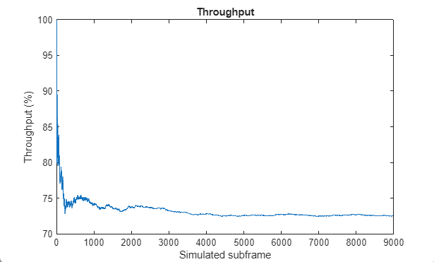
This section calculates the achieved throughput. A figure with the running measured throughput for all simulated subframes is also provided.
maxThroughput = sum(txedTrBlkSizes); % Maximum possible throughput
simThroughput = sum(bitTput,2);      % Simulated throughput

% Display achieved throughput percentage
disp(['Achieved throughput ' num2str(simThroughput*100/maxThroughput) '%'])
Achieved throughput 78.5714%
% Plot running throughput
figure;plot(runningSimThPut*100./runningMaxThPut)
ylabel('Throughput (%)');
xlabel('Simulated subframe');
title('Throughput');

For statistically valid results, the simulation should be run for a larger number of frames. The figure below shows the throughput results when simulating 1000 frames.
Selected Bibliography
3GPP TS 36.101 "User Equipment (UE) radio transmission and reception"
3GPP TR 36.829 "Enhanced performance requirement for LTE User Equipment (UE)"