Configuration for Monitor & Tune and PIL for Renesas RH850 Microcontrollers
Monitor and Tune (External mode)
Monitor and Tune enables you to tune model parameters and evaluate the effects of different parameter values on model results in real-time. When you change parameter values in a model, the modified parameter values are communicated to the target hardware immediately. You can monitor the effects of different parameter values by viewing the output signals on Sink blocks or in the Simulation Data Inspector (SDI). This helps you find the optimal values for performance. This process is called parameter tuning.
Monitor and Tune accelerates parameter tuning. You do not have to rerun the model each time you change the parameters. You can also use Monitor and Tune to develop and validate your model using the actual data and hardware for which it is designed. This software-hardware interaction is not available by solely simulating a model.
Processor-in-the-Loop (PIL)
Executes generated code on the Renesas RH850 processor while the test harness and reference model run on the host. This workflow validates numerical equivalence and timing behavior of generated code before system-level integration.
Prepare a Simulink Model for Monitor & Tune (External mode) or PIL
To prepare your model for Monitor & Tune (External mode) or PIL with serial communication.
In the Simulink® model, select Modeling > Model Settings.
In the Configuration Parameter dialog box, click Hardware Implementation.
Set the Hardware board parameter to
Renesas RH850 U2A Based.The parameter values under Hardware board settings are automatically populated to their default values.
Select External Mode tab.
When
Renesas RH850 U2A Basedis selected as hardware board, Communication interface isXCP on Serial.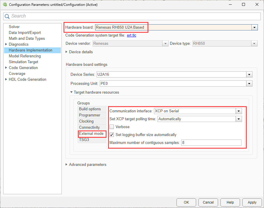
Ensure that you select the Verbose check box to view the external mode execution progress and updates in the Diagnostic Viewer or in the Command Window.
Select the Set logging buffer size automatically parameter to automatically set the number of bytes to preallocate for the buffer in the hardware during simulation. By default, the Set logging buffer size automatically parameter is selected. If you clear this parameter, Logging buffer size (in bytes) parameter becomes available, where you can manually specify the memory buffer size for XCP-based External mode simulation.
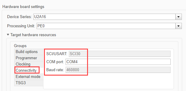
Go to Connectivity tab.
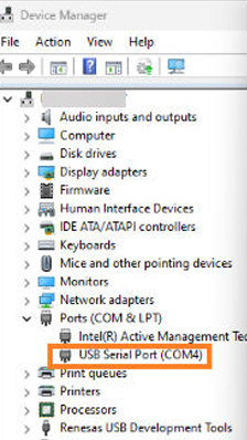
Enter the COM Port number. To find the COM port number, check the Device Manager on your PC.
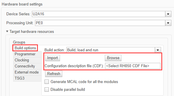
Use the Configuration Description File (CDF) to link your Simulink model with the target hardware configuration and enable MCAL-based peripheral configuration and code generation for your board. The CDF is generated from your AUTOSAR configuration tool and describes the configured MCAL modules (for example, DIO, Port, UART) and their instances for the selected target.
For the selected UART, ensure that the required settings are correctly configured in the CDF file.
For more information, see Configuring MCAL Modules Using DaVinci.
Go to Build options and click Browse to select an existing CDF file. To import an existing file, click Import.
Click Apply and then OK to close the Model Configuration Parameters dialog box.
Specify the corresponding COM port that the target hardware uses.
To see the list of available COM ports on your computer, select Start > Control Panel > Device Manager > Ports (COM & LPT).