Signal Monitoring and Parameter Tuning Using Infineon AURIX TC4x Microcontrollers
This example shows how to use Embedded Coder® Support Package for Infineon® AURIX™ TC4x Microcontrollers in Monitor and Tune mode (External mode simulation) using a Infineon AURIX TC4x hardware board.
Introduction
Monitor and Tune feature enables parameter tuning and data logging while the model is running on the target hardware in real time. When you change parameter values within Simulink®, the modified parameter values are communicated to the target hardware immediately. You can monitor the effects of the parameters tuning activity by viewing the signals on the Simulation Data Inspector and Dashboard Scope. When you are prototyping and developing algorithms, it is useful to monitor signals and tune parameters while the algorithms are running on the hardware.
In this example you will learn how to configure a simple Simulink model to monitor and tune the simulations.
Prerequisites
Complete the Getting Started with Embedded Coder Support Package for Infineon AURIX TC4x Microcontrollers example
Required Hardware
Infineon AURIX TC4x hardware board
Available Model
tc4x_external_mode.slx
Monitor and Tune of Infineon AURIX TC4x
The Infineon AURIX TC4x hardware supports Monitor and Tuning over Serial (ASCLIN) and DAS connectivity interfaces. Simulink provides the following additional features for the targets:
Dashboard objects such as Slider and Dashboard Scope
Simulation Data Inspector (SDI) for visualizing the logged signals
Prepare the model and simulate by following these steps:
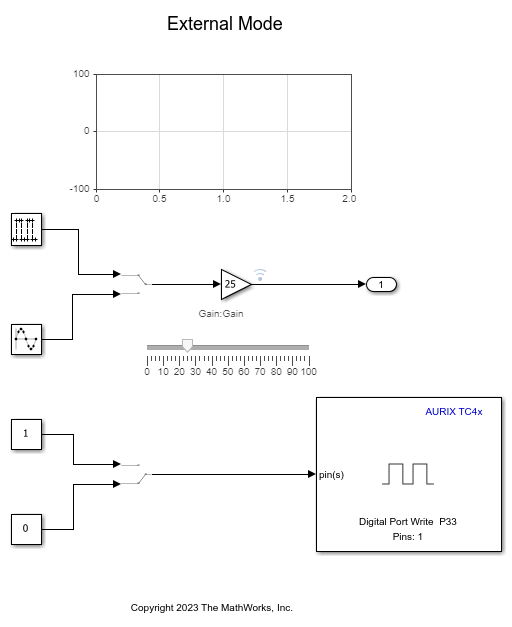
1. Open the tc4x_external_mode.slx model.
2. Specify the COM Port. To see the list of available COM ports on your computer, navigate to Start > Control Panel > Device Manager > Ports (COM &LPT).

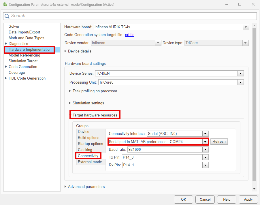
3. In your Simulink model, press Ctrl+E or click Modeling > Model Settings to open Configuration Parameters dialog box. Navigate to Hardware Implementation > Target hardware resources > Connectivity and set Connectivity interface parameter to 'Serial(ASCLIN0)' for external mode simulation.
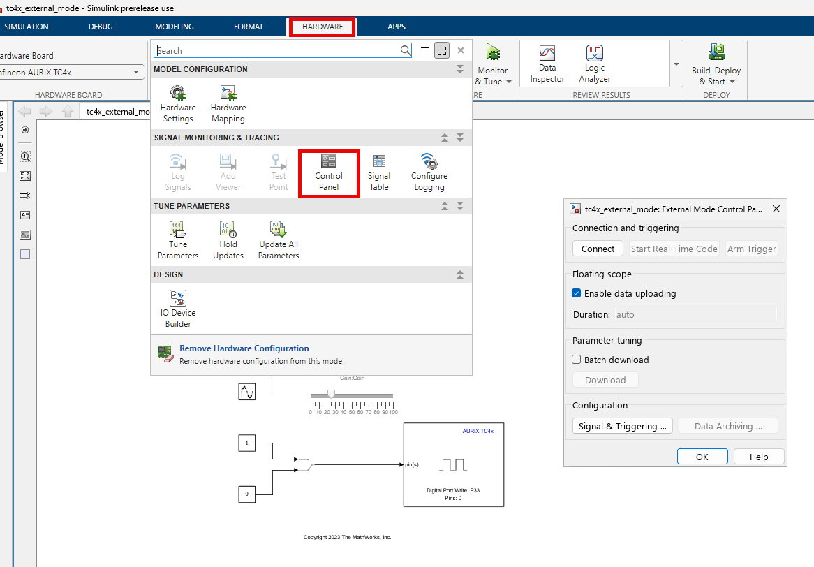
4. Go to Hardware tab, and click Monitor & Tune to configure the model for simulation.

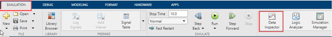
At this point, your model runs on the Infineon AURIX TC4x hardware board and communicates with Simulink from Monitor & Tune. You can select the Simulation > Data Inspector button to view the logged signals.
4. You can tune the parameters and visualize the signals selected for logging by:
Double-clicking the Manual Switch block to change the input source.
Using the Slider to change the signal gain.
Double-clicking the Scope block to view the simulation results.
Double-clicking the Manual Switch block to turn ON and OFF the LED.
The model runs in real-time on the target while performing these actions.
5. Stop Monitor & Tune simulation by clicking the Stop.
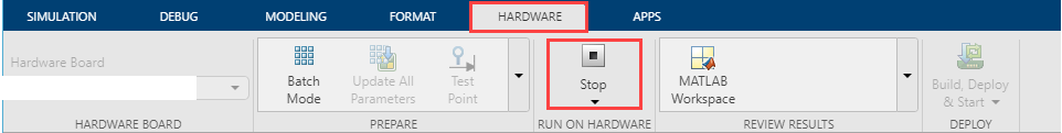
Stopping the Monitor & Tune simulation terminates the execution of the code running on the Infineon AURIX TC4x hardware board.
Note: At any point during the course of the simulation, you can open the External Mode Control Panel. The Hardware > control panel provides more options, such as the ability to connect or disconnect to the target without terminating the execution of the generated code.
Known Limitations
1. External mode simulation on parallel processing unit is not supported.
2. DAS connectivity interface is not supported for the external mode simulation.
Other Things to Try
Run the example on different Infineon AURIX TC4x Microcontrollers by changing the package class and pinout options and analyze the results.