TMADC Peripheral Configuration
Map TMADC peripherals in the Infineon AURIX model to peripheral registers in the MCU
Since R2022b
Description
Add-On Required: This feature requires the Embedded Coder Support Package for Infineon AURIX TC4x Microcontrollers add-on.
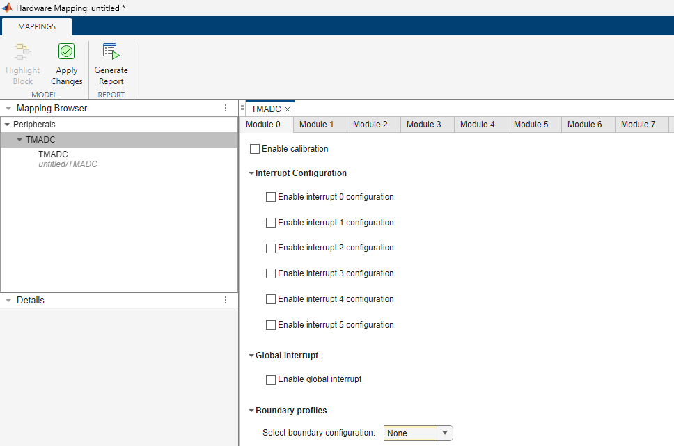
View and edit the map of peripherals in the Infineon® AURIX™ model to the hardware peripherals.
Using the Peripheral Configuration tool, you can:
View and edit configuration parameters for TMADC peripheral block.
Configure the global parameters. To set the group peripheral, select peripheral in Browser > Peripherals >
TMADC. For more, see Map Tasks and Peripherals Using Hardware Mapping.Check for any conflicts between peripherals.
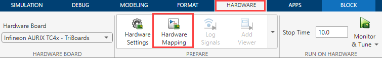
Open the TMADC Peripheral Configuration
In the Hardware tab, click Hardware Mapping.
Examples
Parameters
Global parameters > Module #
Enables the TMADC calibration for the module.
Global parameters > Module # > Interrupt Configuration
Select the interrupt configuration for the TMADC module. This parameter enables the interrupt# for the module.
Select the event operation for TMADC module.
Dependencies
To enable the Event operation parameter, select the Enable interrupt # configuration parameter.
Select the event for the TMADC module.
Dependencies
To enable the Event operation parameter, select the Enable interrupt # configuration parameter.
This read-only parameter displays the source name of the interrupt as
TMADCx_Interrupt_y, where x is the Module
x and y is the interrupt configuration you enable in the Module
x tab of Hardware Mapping window.
Dependencies
To view the Interrupt Event source name, select the Enable interrupt # configuration parameter.
Global parameters > Module # > Global interrupt
This parameter enables the global interrupt for the TMADC module.
Select the event operation for TMADC module.
Dependencies
To enable the Event operation parameter, select the Enable global interrupt parameter.
Select the global event for the TMADC module.
Dependencies
To enable the Event operation parameter, select the Enable global interrupt parameter.
Select the global service request for the TMADC module.
Dependencies
To enable the Select global service request parameter, select the Enable global interrupt parameter.
Select the event operation for global interrupt.
Dependencies
To enable the Global event operation parameter, select the Enable global interrupt parameter.
This read-only parameter displays the source name of the interrupt as
TMADC_Global_Interrupt_x. This signifies the interrupt
configuration you enable in the Module x tab of Hardware Mapping
window.
Dependencies
To view the Event source name, select the Enable global interrupt parameter.
Global parameters > Module # > Boundary profiles
Select boundary profiles for the TMADC module.
Global parameters > Module # > Profile #
Specify the upper limit for boundary profile.
Dependencies
To set the Upper limit parameter for profile #, set the
Select boundary configuration parameter as either
Profile-# or Both
profiles.
Specify the lower limit for boundary profile.
Dependencies
To set the Lower limit parameter for profile #, set the
Select boundary configuration parameter as either
Profile-# or Both
profiles.
Select this parameter to enable boundary flag for TMADC module.
Dependencies
To enable the Enable boundary flag parameter for profile #,
set the Select boundary configuration parameter as either
Profile-# or Both
profiles.
Select the appropriate result register ranging between Result
0 through Result 15 for the boundary
flag.
Dependencies
To set the Boundary result parameter, select the Enable boundary flag parameter.
Global parameters > Module # > Boundary flag- # connection
Specify the number of boundary flag connections.
Dependencies
To set this parameter, select the Enable boundary flag parameter.
Module
Select the TMADC module 0 through
7 on the hardware board.
Provides the number of channels selected for the TMADC module. The number of channels selected depends on the input provided on the TMADC block.
Input group
This parameter enables the group functionality for the available channels.
Disabling this parameter enables the Operating mode parameter and options related to trigger and result registers in the Input # tab.
Note
This parameter is enabled only when number of channels on the block mask is more than one.
Select the operating mode for TMADC channel group.
Note
You must set the Operating mode for the group parameter to
One shot to view and configure the trigger related
parameters.
Dependencies
To enable the Operating mode for the group parameter, select the Enable channel group parameter.
Select the TMADC trigger source for channel group.
Dependencies
To enable the Trigger source for the group parameter, select
the Enable channel group parameter and set Operating
mode for the group to One shot.
Select the TMADC hardware trigger source for channel group.
Dependencies
To enable the Source of hardware trigger # for the group
parameter, select the Enable channel group parameter and set
Trigger source for the group to Hardware trigger
# or Both hardware triggers.
Select the TMADC hardware trigger for channel group.
Dependencies
To enable the Source of hardware trigger # for the group
parameter, select the Enable channel group parameter and set
Trigger source for the group to Hardware trigger
# or Both hardware triggers.
Select the TMADC hardware trigger edge for channel group.
Dependencies
To enable the Source of hardware trigger # for the group
parameter, select the Enable channel group parameter and set
Trigger source for the group to Hardware trigger
# or Both hardware triggers.
Specify the trigger delay in nano seconds for the TMADC channel group.
Dependencies
To enable this parameter, set the Trigger source for the
group parameter value to either Hardware trigger # or
Both hardware triggers.
Select the result register ranging between Result 0
through Result 15 for TMADC channel group.
Dependencies
To enable the Select result register parameter, select the Enable channel group parameter.
Select this parameter to enable the register to wait and read the TMADC channel # result registers.
Dependencies
To enable this parameter, select the Enable channel group
parameter and set the Trigger source for the group parameter to
 Hardware trigger
                #
or Both Hardware
triggers.
Input #
Select the TMADC pin for conversion.
Select the input mode for the pin(s).
Select the pin speed for TMADC.
Select the pin voltage level.
This parameter is read-only.
This read-only parameter indicates the channel corresponding to the pin selected.
Specify the sampling duration in nano seconds for the TMADC channel.
Select the Successive-approximation-register (SAR) core for TMADC channel.
Select the operating mode for TMADC channel.
Note
You must set the Operating mode parameter to One
shot to view and configure the Trigger related
parameters.
Dependencies
To enable the Operating mode parameter in Input
#, set the block parameter Mode to either
Trigger and read or Trigger
only, and disable the Operating mode parameter in
the in Input group tab.
Input # > Trigger
If the Mode in block parameters is set to Trigger
and read, select the TMADC trigger source for channel. If the
Mode is set to Trigger only, then this
is a read-only parameter set to Software trigger.
Note
To ensure correct TMADC behaviour for the Software
trigger option, you must set the Sample time parameter of the TMADC block to 2e-6 or
greater.
If the Mode in block parameters is set to Trigger
and read, select the appropriate trigger source through which conversion
initiates.
Dependencies
To enable the Source of hardware trigger# parameter, set the
Trigger source to either Hardware trigger #
or Both hardware triggers.
If the Mode in block parameters is set to Trigger
and read, select the appropriate trigger signal through which conversion
initiates.
Dependencies
To enable the Hardware trigger# parameter, set the
Trigger source to either Hardware trigger #
or Both hardware triggers.
If the Mode in block parameters is set to Trigger
and read, select the appropriate trigger edge through which conversion
initiates.
Dependencies
To enable the Hardware trigger edge# parameter, set the
Trigger source to either Hardware trigger #
or Both hardware triggers.
Specify the trigger delay in nano seconds for the TMADC channel.
Dependencies
To enable this parameter, set the Trigger source to either
 Hardware trigger
                #
or Both hardware
triggers.
Input # > Result
Select the result register for TMADC channel.
Dependencies
To enable the result related parameter Select result
register, set the Mode in block parameters as either
Read results only or Trigger and
read.
Select this parameter to enable the register to wait and read the TMADC channel # result registers.
Dependencies
To enable this result related parameter, set the Mode in
block parameters toTrigger and read or Read
only. In the Trigger and read mode, set the
Trigger source to Hardware trigger #
or Both Hardware triggers.
Input # > Events
Select the result interrupt for the TMADC channel.
Dependencies
To enable this parameter, enable the interrupt configuration and set the
Event selection parameter to Result
in the global parameters.
Select error interrupt for the TMADC channel.
Dependencies
To enable this parameter, enable the interrupt configuration and set the
Event selection parameter to Error
in the global parameters.
Input # > Boundary
Select the boundary profile for TMADC channel # result.
Dependencies
To enable the Select boundary profile parameter, set the
Select boundary configuration parameter in global parameters to
either Profile-# or Both
profiles.
Select the boundary type for TMADC channel.
Dependencies
To enable the Boundary selection parameter, set the
Select boundary profile parameter as Boundary
profile-#.
Select the boundary mode for TMADC channel result.
To enable the Boundary mode parameter, set the Select
boundary profile parameter as Boundary
profile-#.
Enables the hysteresis condition for boundary selection for TMADC channel result.
Dependencies
To enable the Enable hysteresis parameter, set the
Boundary selection to Both bound.
Select the boundary interrupt for TMADC channel result.
Dependencies
To enable this parameter, enable the interrupt configuration and set the global
parameter Event selection to
Boundary.
Version History
Introduced in R2022b
MATLAB Command
You clicked a link that corresponds to this MATLAB command:
Run the command by entering it in the MATLAB Command Window. Web browsers do not support MATLAB commands.
Select a Web Site
Choose a web site to get translated content where available and see local events and offers. Based on your location, we recommend that you select: .
You can also select a web site from the following list
How to Get Best Site Performance
Select the China site (in Chinese or English) for best site performance. Other MathWorks country sites are not optimized for visits from your location.
Americas
- América Latina (Español)
- Canada (English)
- United States (English)
Europe
- Belgium (English)
- Denmark (English)
- Deutschland (Deutsch)
- España (Español)
- Finland (English)
- France (Français)
- Ireland (English)
- Italia (Italiano)
- Luxembourg (English)
- Netherlands (English)
- Norway (English)
- Österreich (Deutsch)
- Portugal (English)
- Sweden (English)
- Switzerland
- United Kingdom (English)