FPGA-Based Monopulse Technique: Code Generation
This example shows the second half of a workflow to generate HDL code for a monopulse technique and verify that the generated code is functionally correct.
The first example in the workflow, FPGA-Based Monopulse Technique: Algorithm Design, shows how to develop an algorithm in Simulink® suitable for implementation on hardware, such as a field programmable gate array (FPGA), and how to compare the output of the fixed-point implementation model to that of the corresponding floating-point behavioral model.
This example uses HDL Coder™ to generate HDL code from the Simulink model developed in part one and verifies the HDL code using HDL Verifier™. HDL Verifier is used to generate a cosimulation test bench model to verify the behavior of the automatically generated HDL code. The test bench uses ModelSim® for cosimulation to verify the automatically generated HDL code.
The Phased Array System Toolbox™ Simulink blocks model operations on floating-point data and provides the behavioral reference model. This behavioral model is used to verify the results of the implementation model and the automatically generated HDL code.
HDL Coder™ generates portable, synthesizable Verilog® and VHDL® code for Simulink blocks that support HDL code generation.
HDL Verifier lets you test and verify Verilog and VHDL designs for FPGAs, ASICs, and SoCs. This example verifies HDL generated from the Simulink model against a test bench running in Simulink using cosimulation with an HDL simulator.
Implementation Model
This example assumes that you have a Simulink model that contains a subsystem with a monopulse technique designed using Simulink blocks that use fixed-point arithmetic and support HDL code generation. FPGA-Based Monopulse Technique: Algorithm Design shows how to create such a model.
To start with a new model, run the hdlsetup (HDL Coder) function to configure the Simulink model for HDL code generation.
Comparing Results of Implementation Model to Behavioral Model
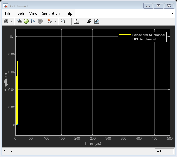
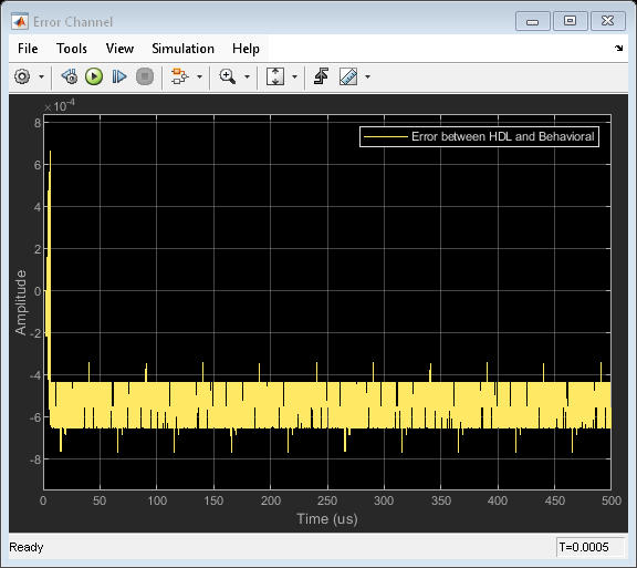
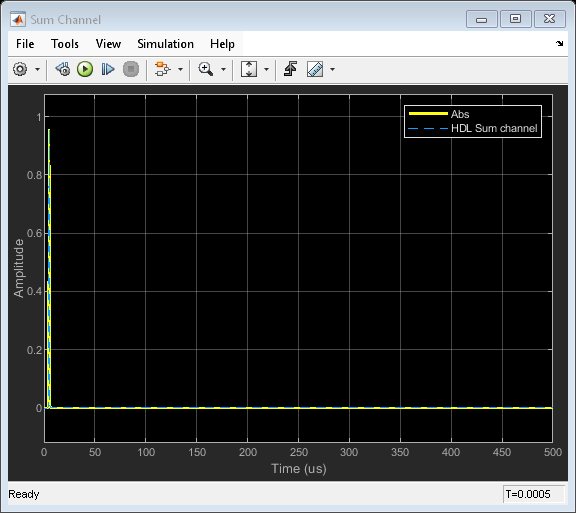
Run the model created in the FPGA-Based Monopulse Technique: Algorithm Design example to display the results. You can run the Simulink model by clicking the Play button or calling the sim command on the MATLAB® command line. Use the Time Scope blocks to compare the output frames visually.
modelname = 'SimulinkDDCMonopulseHDLWorkflowExample';
open_system(modelname);

sim(modelname);


Code Generation and Verification
This section shows how to generate HDL code for a DDC and monopulse technique and verify that the generated code is functionally correct. The behavioral model provides the reference values to ensure that the output from HDL is within tolerance limits.
After the fixed-point implementation is verified and the implementation model produces the same results as your floating-point behavioral model, you can generate HDL code and test bench. For code generation and test bench, set these HDL Code Generation parameters in the Configuration Parameters dialog.
Target: Xilinx Vivado synthesis tool; Virtex7 family; Device xc7vx485t; package ffg1761, speed -1; and target frequency of 300 MHz.
Optimization: Clear all optimizations.
Global Settings: Set the Reset type to Asynchronous.
Test Bench: Select HDL test bench and Cosimulation model.
HDL Code Generation and Test Bench Creation
After Simulink Model Settings are updated, you can use HDL Coder to generate HDL Code for the HDL Algorithm subsystem and use HDL Verifier to generate test bench model.
Use these commands to generate HDL code and test bench.
makehdl([modelname '/DDC and Monopulse HDL']);   % Generate HDL code
makehdltb([modelname '/DDC and Monopulse HDL']); % Generate Cosimulation test bench
Since the model has accounted for pipelining in the multiplications, and disabled code gen optimizations, there are no extra delays added to the model. To align the output of the behavioral model with the implementation model and the cosimulation, you must compensate for the pipeline delays. A delay of ( ) is added to the output of the digital comparator. This delay is added to compensate for the latency in the DDC chain. Of the 220 units delay, 215 unit delays compensates for the latency in the DDC chain and 5 units corresponds to the monopulse sum and difference subsystem.
When you generate the test bench, the tool creates a new Simulink model in your working directory named gm_<modelname>_mq. The model contains a ModelSim Simulator block and looks like this:

To open the test bench model, use this command.
modelname = ['gm_',modelname,'_mq'];
open_system(modelname);
Open ModelSim and run the cosimulation model to display the simulation results. You can click on the Play button on the top of Simulink canvas to run the test bench or run it from the MATLAB® command line.
Use this command to run the test bench.
sim(modelname);
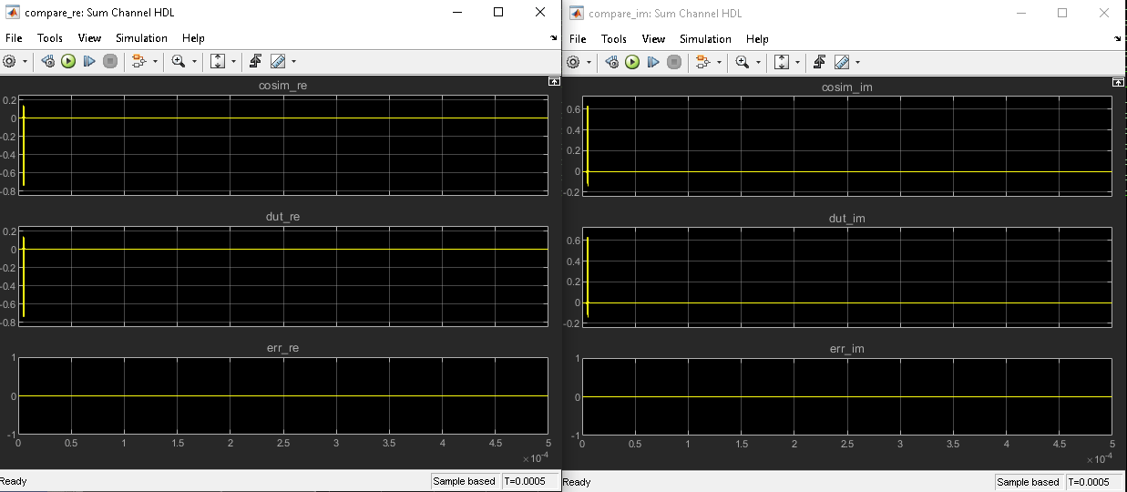
The Simulink test bench model populates the Questa® Sim waveform with the HDL model's signal and Time Scopes in Simulink. The figures show examples of the results in Questa Sim and Simulink scopes.
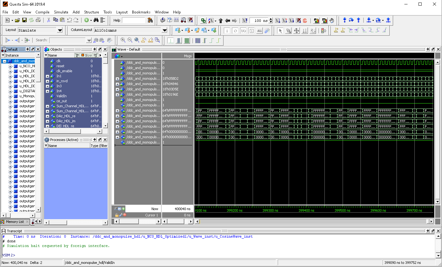
The Simulink scope shows real and imaginary parts for both the cosimulation and design under test (DUT) as well as the error between them.
The Compare subsystem in the test bench model contains scopes that compare the results of the cosimulation. The Compare subsystem is at the output of the DDC and Monopulse HDL_mq subsystem.
Use this command to open the subsystem with the scopes.
open_system([modelname,'/Compare/Assert_Sum Channel HDL'])
Summary
The example showed how to generate HDL code and a cosimulation test bench for a fixed-point monopulse technique subsystem in Simulink that contains blocks that support HDL code generation. The example showed how to setup and open ModelSim to cosimulate the HDL code and compare Simulink simulation results to the output generated by the HDL simuation.