Harris Accelerates Verification of Signal Processing FPGAs
“HDL Verifier provided a direct cosimulation interface between our MATLAB model and our logic simulator, which enabled us to verify our design earlier, identify problems faster, complete more tests, and compress our entire development cycle.”
Challenge
Solution
Results
- Functional verification time cut by more than 85%
- 100% of planned test cases completed
- Design implemented defect-free

Engineers at Harris Corporation are accustomed to delivering sophisticated FPGA-based signal processing systems within tight schedules. To meet their customers’ often stringent requirements and their own quality standards, the engineers thoroughly verify the HDL design of each system before it is synthesized.
In the past, HDL verification required several manual steps. Harris engineers have automated the process by using HDL Verifier™ to provide a bidirectional link between the MATLAB® system model and the HDL design simulated in Cadence® Incisive®. The new process eliminates ambiguity between the algorithm specification and HDL verification, reduces duplication of effort, and improves communication between system and HDL engineers.
“Cosimulation with MATLAB and HDL Verifier not only made it easier to simulate at the subsystem level, it also enabled us to verify the overall system more completely,” says Jason Plew, senior engineer at Harris. “We greatly reduced the time needed to develop subsystem test benches, which enabled us to verify and debug our designs much earlier.”
Challenge
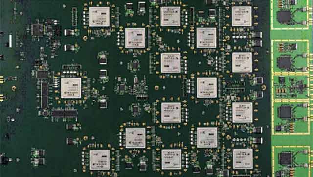
Harris engineers needed to design and verify a signal processing system that spanned multiple Xilinx® Virtex® FPGAs. In this labor-intensive process, once a fixed-point model of the subsystem had been simulated, the team exported large text files containing stimulus data and expected results from those simulations and imported them into Cadence Incisive. An experienced engineer then wrote test benches in HDL to read in the data, apply the stimulus, and verify the results. If the results did not match, the team had to delve into the massive results files to find out where and why the simulation failed. For each change in the characteristics of the test, they had to re-export the simulation data, which required 8 hours of tedious manual work.
“We spent a considerable amount of time churning through manual steps for each subsystem, and as a result, we only had time to complete 30% of the desired system-level test cases before our deadline,” Plew recalls.
Harris needed a way to drive the input signals in the logic simulator directly, eliminating the need to write the HDL test benches and the overhead of managing huge text files of test data.
Solution
Harris engineers modeled and simulated their signal processing systems in MATLAB. The MATLAB model became a reusable test bench that they could use interactively to cosimulate with their Cadence Incisive simulator using HDL Verifier.
With MATLAB and DSP System Toolbox™, the engineers developed an ideal floating-point model of the baseband signal processing data path, which they used to verify that the design met the functional requirements.
After converting the model to fixed point, they optimized their algorithms for implementation in hardware. Additional simulations were performed in MATLAB to ensure that the fixed-point implementation performed within specifications.
Using the fixed-point model as an executable specification, Harris engineers then implemented the system in HDL.
The team used HDL Verifier to enable the MATLAB code to act as the test bench for the implementation. Via the cosimulation interface, MATLAB was used to supply stimulus to and analyze the results from the HDL simulation.
To accelerate the execution of multiple test cases, Harris engineers developed a MATLAB control script that managed multiple parallel cosimulations across a Linux computing grid.
The team used this approach to rapidly verify individual subsystems as well as the overall signal processing chain before synthesizing and successfully demonstrating the device. Harris engineers have begun applying the same approach on other projects, including one that requires a million-point fast Fourier transform.
Results
- Functional verification time cut by more than 85%. “It used to take an experienced engineer about 8 hours to prepare a subsystem test bench,” says Plew. “With HDL Verifier, we can create one in an hour, and because MATLAB generates the stimulus and performs the analysis, we have all the test results ready in MATLAB for postprocessing.”
- 100% of planned test cases completed. “Our previous process was so complex that we often performed little verification at the subsystem level, and our schedule kept us from running more than 30% of the desired test cases at the system level,” says Plew. “With MathWorks tools, we generated and simulated 100% of those test cases using an automated process that enables us to find most defects at the subsystem level.”
- Design implemented defect-free. “We eliminated weeks of lab debug time because we had so thoroughly verified the design by using HDL Verifier to cosimulate our HDL code in MATLAB and Cadence Incisive,” Plew notes. “In fact, the data path elements of the FPGA performed as designed right from the start.”