Model-Based Design of Magnetic Levitation Guide Control System for Ultraprecision Machining
By Per Schreiber, Institute of Production Engineering and Machine Tools (IFW), Leibniz Universität Hannover
“Model-Based Design was instrumental in achieving our initial objective: demonstrating a first-of-its-kind, fully functional prototype for ultraprecision machining with magnetic levitation guides.”
Ultraprecision machining plays an essential role across a wide range of applications, including medical devices, optics, metrology, and microelectromechanical systems. The guide technology used to move machine components and workpieces with submicron precision has a significant effect on the overall accuracy and speed of the machining process. Two of the most used guide technologies—hydrostatic and aerostatic drives—offer smooth movement as well as damping that suppresses vibration. However, implementing and maintaining these guides can be both costly and complex, particularly for applications requiring multiple degrees of freedom.
At the Institute of Production Engineering and Machine Tools at Leibniz Universität Hannover, my colleague and I have implemented a new guiding technology for ultraprecision machining based on magnetic levitation. This approach is designed to address some of the drawbacks of existing guide technologies while maintaining exceptionally high precision. Electromagnetic levitation guides have the potential to significantly increase productivity in ultraprecision machining as they allow for additional degrees of freedom and active vibration damping so that production velocities can be increased. Using our prototype, we machined an aluminum workpiece with depths of cut varying from 3 µm to 7 µm, achieving a surface roughness of less than 45 nm Sa (Figure 1). We used Model-Based Design to build the real-time control system required to achieve this degree of precision—modeling and simulating the system in Simulink® before using Simulink PLC Coder™ to generate IEC 61131-3 Structured Text for deployment on a Beckhoff® Industrial PC. This workflow enabled us to accelerate development while minimizing tedious and labor-intensive manual coding of structured text.
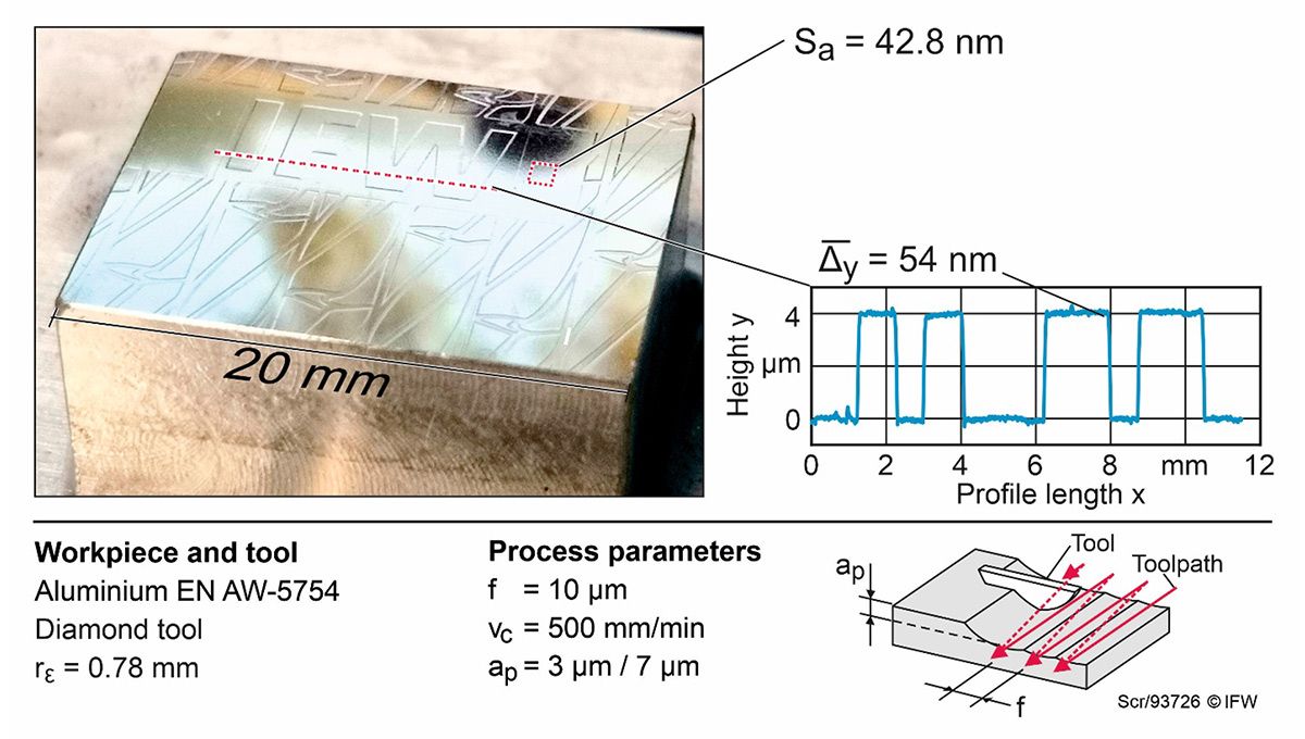
Figure 1. An aluminum workpiece machined using electromagnetic levitation guide technology.
Axis Control with Magnetic Levitation
To show the feasibility of applying levitation technology in ultraprecision cutting, we designed and built a prototype that includes all the relevant functionalities of a complete three-axis ultraprecision milling machine. In contrast to a single-axis guiding prototype, we can evaluate the guiding technology in actual ultraprecision cutting processes. The design of our prototype system includes three macro-level axes (x, y, and z) as well as five additional fine-positioning degrees of freedom (DoF) (Figure 2). These additional DoFs—managed by the electromagnetic levitation guide—support more precise positioning along the x- and z-axes as well as rotational positioning (roll, pitch, and yaw). In the machining process, the macro-axes x and z provide the motion for feed while the y-axis is used for pre-adjustment of the spindle and tool position. Positions along these axes are measured with linear encoders.

Figure 2. The ultraprecision machining prototype showing larger scale positioning axes on the left (x, y, and z) and small-scale positioning using electromagnetic actuators on the right.
Fine-positioning control is achieved via 12 electromagnetic actuators used to levitate the workpiece and 12 capacitive sensors used to measure the gap distances between the workpiece slide and each electromagnet. The orientation of the slide in the six degrees of freedom is derived from those measurements.
The control architecture is similarly organized around the macro-level and fine-positioning aspects of the prototype. One control subsystem is dedicated to the major x-, y-, and z-axes, while a second subsystem is used for the electromagnetic levitation system (Figure 3). This controller, which runs at 20 kHz, the maximum sampling rate supported by the Beckhoff Industrial PC we selected for the prototype, manages the ultraprecision positioning as well as maintaining sufficient opposing force via the electromagnets to enable the tool to cut the workpiece.

Figure 3. Prototype control architecture.
Modeling and Simulating Controllers
We modeled both the macro-level and fine-positioning control systems in Simulink. The macro-level system is relatively straightforward. Based on a cascade control loop with proportional-integral controllers, it outputs current set points based on position and velocity measurements from the x-, y-, and z-axis encoders (Figure 4).

Figure 4. Simulink model of the z-axis macro-level controller.
The fine-positioning control system includes a separate proportional-integral-derivative (PID) controller for each of the five degrees of freedom. This controller calculates current set points for the electromagnets based on inputs from the prototype’s 12 capacitive sensors. Since electromagnetic levitation is inherently unstable in the open-loop state, simulation is required to determine an initial set of control parameters before testing it on hardware. In preparation, we created a plant model that captured characteristics of capacitive sensors, transport delays, and the nonlinear relationship between the current and the gap separating an electromagnet from the workpiece, among other effects. We ran a wide range of closed-loop simulations in Simulink with our controller and plant model to evaluate the control system’s robustness and made several enhancements to improve performance as we worked.
Generating Structured Text and Testing the Prototype
Once we had verified the control design via simulation, we generated IEC 61131-3 structured text from our Simulink models using Simulink PLC Coder. We then imported, compiled, and deployed the control application to the Beckhoff Industrial PC connected to the sensors and actuators of our hardware prototype. Our initial tests were promising, but as expected we needed to adjust some parameters in the fine-positioning controller to improve performance. These adjustments were needed to account for manufacturing variances in the characteristics of the electromagnets—which can affect the approximately 200-micrometer gaps between the magnets at the back iron—as well as other tolerances in the assembly of the machine. After making the necessary changes in the model and verifying them via simulation, we regenerated structured text from the model and performed further testing to verify the ultraprecision machining capabilities of the prototype (Figure 5).
Next-Generation Improvements
Model-Based Design was instrumental in achieving our initial objective: demonstrating a first-of-its-kind, fully functional prototype for ultraprecision machining with magnetic levitation guides. We are continuing to use Simulink and Simulink PLC Coder for modeling, simulation, and code generation as we work on the next-generation prototype. In this new machine, among a number of improvements, we have incorporated six-degree-of-freedom optical position sensors that replace the capacitive gap sensors. Because these sensors are both less susceptible to electromagnetic noise, we expect this change to further increase the precision of this version of the machine.
Published 2024