Developing Power Converter Control Software for the J-PARC Particle Accelerator
By Yoshinori Kurimoto, High Energy Accelerator Research Organization (KEK)
Results from the T2K experiment suggest that neutrino oscillations may hold the key to understanding a fundamental question about the universe: why it contains vastly more matter than antimatter when the Big Bang is believed to have produced equal amounts of both. The T2K experiment is a long baseline neutrino oscillation experiment in which neutrinos and antineutrinos produced at the Japan Proton Accelerator Research Complex (J-PARC) are observed in the SuperKamiokande detector located 295 km away. Finding a difference in oscillations between neutrinos and antineutrinos would provide an essential clue about how our universe was formed.
The largest task of the experiment is the production of numerous neutrinos and antineutrinos. In the T2K experiment, neutrinos are created with the J-PARC proton accelerator by accelerating protons to near light speed and smashing them into a target material. To expand our investigation of neutrino oscillations, we need to produce more neutrinos by increasing the rate at which we supply protons via the accelerator. Then, once the proton beams enter the main ring, we need more powerful electromagnets to control the beams as they travel around the ring (Figure 1).
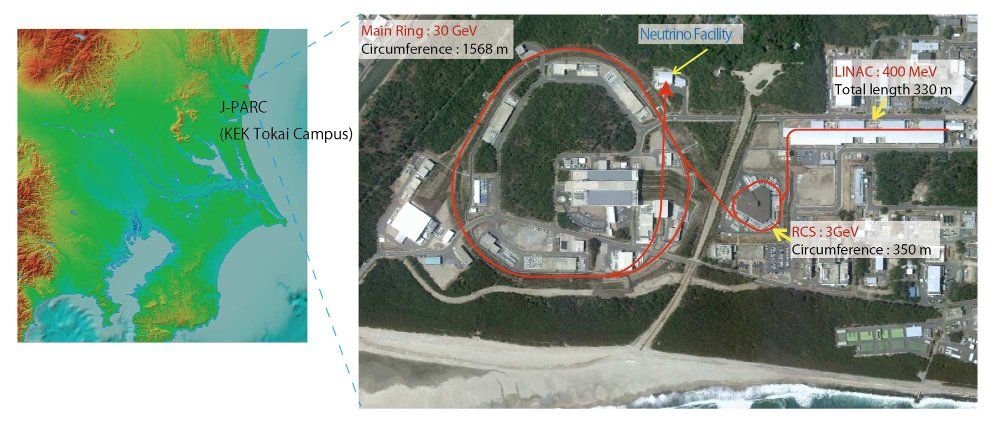
Figure 1. Bird's-eye view of J-PARC showing the main ring and path of proton beams in red.
None of the manufacturers we usually worked with were able to engineer a power converter that could deliver the power needed for these stronger electromagnets within our budget. We therefore decided to help the engineering effort by developing the control software ourselves.
Neutrino research is an area of intense competition, and we need to keep pace with labs in the U.S. and Europe that are engaged in similar research. To speed development and keep down costs, we developed the power supply control software using Model-Based Design with Simulink® and deployed it to an FPGA using HDL Coder™. Model-Based Design enabled us to develop the control software at a cost 60% less than the estimates provided by major manufacturers and to cut development time by more than 50%.
Our Challenge: Almost Double the Voltage Supplied to J-PARC Electromagnets
To appreciate how important a larger power supply was to our research, it helps to understand the process for generating and detecting neutrinos at J-PARC. First, we use a linear accelerator to accelerate negative hydrogen ions to about 400 million electron volts (MeV). With the J-PARC synchrotron, we convert the ions to protons and accelerate the protons to 1.3 billion electron volts (GeV) in J-PARC’s small ring, which is about 350 meters in circumference. The protons are then directed to the main ring, (about 1.5km in circumference), where they are accelerated to 30 GeV before being targeted to the neutrino generation facility. In the final stage, the neutrinos are observed at the neutrino observatory located under Mount Ikeno, 295 km away.
In the main ring (Figure 2), bending and quadrupole electromagnets control the proton beams’ trajectory by applying precisely synchronized magnetic fields.
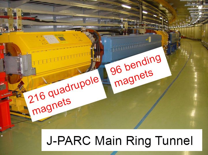
Figure 2. The J-PARC main ring, showing the bending and quadrupole electromagnets used to control the proton beam trajectory.
For our upcoming experiments, we need to supply more protons, which means reducing the amount of time needed to switch (or cycle) the electromagnet from 2.48 seconds to 1.3 seconds. The time required to switch an electromagnet is inversely proportional to the voltage applied, which means that we have to almost double the voltage, corresponding to the total output power of approximately 100 MW—more than the electrical grid is capable of providing.
Designing and Implementing the Power Converter Controller
The converter has two main components: a three-phase AC-to-DC voltage converter that is used to charge large capacitors, and a chopper that supplies power from the capacitors to the electromagnet (Figure 3).
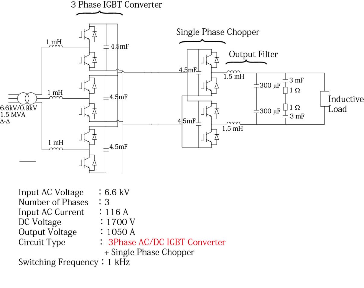
Figure 3. Schematic of the new electromagnet power supply unit.
One of our goals in designing the power converter controller was to verify our design through simulation before performing tests on actual hardware. We started by creating a plant model of the power supply’s three-phase AC/DC converter and chopper using Simulink, Simscape™, and Simscape Electrical™. We then created a complete system model of the controller and plant (Figure 4).
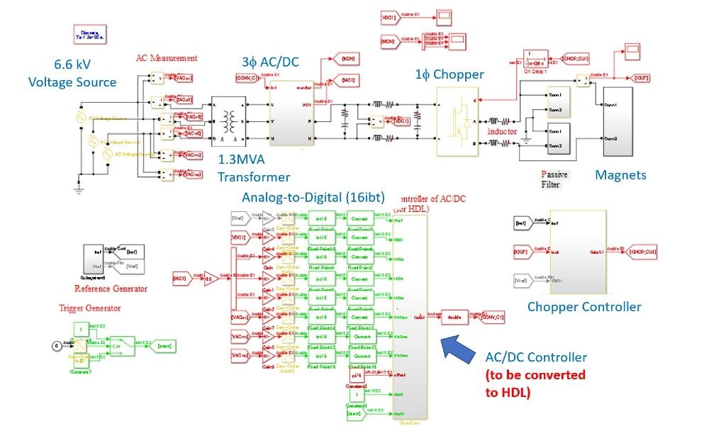
Figure 4. Simulink model of the power converter and its controller.
The controller model includes subsystems for DC voltage control, active power control, reactive power control, and pulse-width modulation, as well as elements for performing the direct-quadrature-zero transformations between three-phase signals and the direct-quadrature (dq0) reference frame (Figure 5).
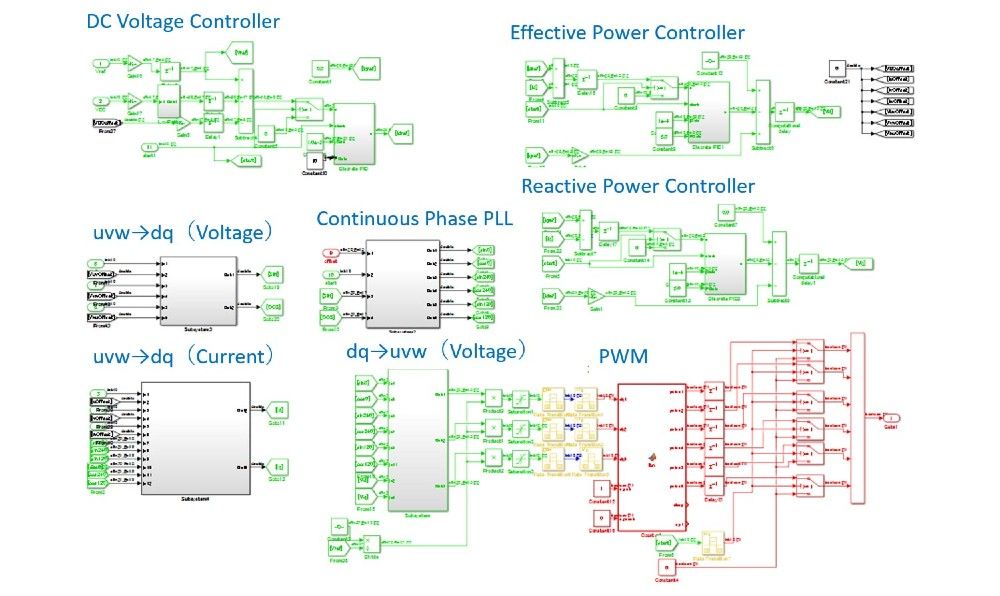
Figure 5. Simulink model of controller subsystems.
We selected an FPGA for the first version of our design because we needed to control multiple modules, and the input/output capabilities of the FPGA made it preferable to a microcontroller with relatively few inputs and outputs. One advantage of Model-Based Design is that, should we choose to redeploy on a microcontroller in the future, we will be able to generate C code from our existing controller design with Embedded Coder® and be up and running on a new target very quickly.
After running simulations to verify the design and tune control parameters, we generated synthesizable Verilog® code from our controller model using HDL Coder.
We deployed this code to a device from Intel’s Cyclone® FPGA family and tested it using a smaller version of the production power supply. We verified that the waveforms from this setup matched the waveforms shown in the simulation results, with only minor deviations.
Finally, we tested and verified the FPGA controller on the actual power converter hardware.
We have completed the implementation of the first power converter unit equipped with our FPGA-based controller. We are currently building the remaining units needed for the entire main ring at J-PARC. We expect to begin neutrino oscillation experiments with this new setup when construction of these units is completed.
Published 2018